
▶️ P-type semiconductors are created by doping an intrinsic semiconductor with an electron acceptor element during manufacture. The term p-type refers to the positive charge of a hole. As opposed to n-type semiconductors, p-type semiconductors have a larger hole concentration than electron concentration. In p-type semiconductors, holes are the majority carriers and electrons are the minority carriers. A common p-type dopant for silicon is boron or gallium. For p-type semiconductors the Fermi level is below the intrinsic semiconductor and lies closer to the valence band than the conduction band.
▶️ Examples: boron, aluminium, gallium, etc.
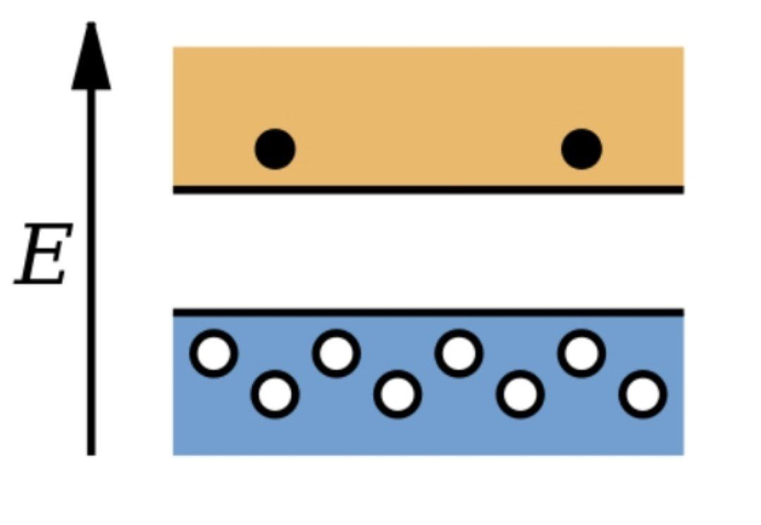
▶️ The image down below depicts the band structure of a p-type semiconductor. Dark circles in the conduction band are electrons and light circles in the valence band are holes. The image shows that the holes are the majority charge carrier.
━━━━━━━━━━━━
☢ @Physics ⚡| @Education 📖
▶️ Examples: boron, aluminium, gallium, etc.
▶️ The image down below depicts the band structure of a p-type semiconductor. Dark circles in the conduction band are electrons and light circles in the valence band are holes. The image shows that the holes are the majority charge carrier.
━━━━━━━━━━━━
☢ @Physics ⚡| @Education 📖
👍39❤8🔥8😱3
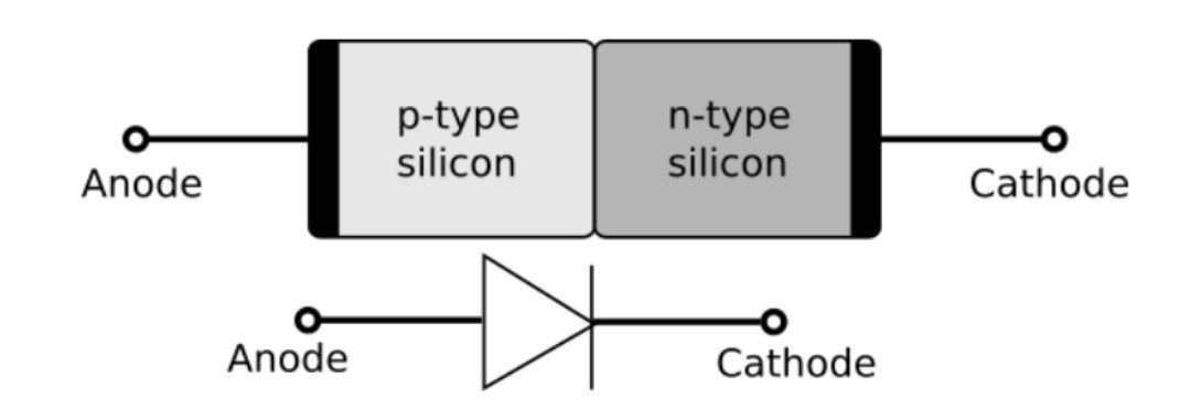
▶️ A p–n junction is a boundary or interface between two types of semiconductor materials, p-type and n-type, inside a single crystal of semiconductor. The "p" (positive) side contains an excess of holes, while the "n" (negative) side contains an excess of electrons in the outer shells of the electrically neutral atoms there. This allows electrical current to pass through the junction only in one direction. The p-n junction is created by doping, for example by ion implantation, diffusion of dopants, or by epitaxy (growing a layer of crystal doped with one type of dopant on top of a layer of crystal doped with another type of dopant). If two separate pieces of material were used, this would introduce a grain boundary between the semiconductors that would severely inhibit its utility by scattering the electrons and holes.
▶️ The image down below depicts a p–n junction. The triangle in the circuit symbol corresponds to the p side.
━━━━━━━━━━━━
☢ @Physics ⚡| @Education 📖
▶️ The image down below depicts a p–n junction. The triangle in the circuit symbol corresponds to the p side.
━━━━━━━━━━━━
☢ @Physics ⚡| @Education 📖
👍30🔥10❤8
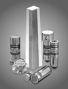
A scintillator is a material that exhibits scintillation, the property of luminescence, when excited by ionizing radiation. Luminescent materials, when struck by an incoming particle, absorb its energy and scintillate (i.e. re-emit the absorbed energy in the form of light). Sometimes, the excited state is metastable, so the relaxation back down from the excited state to lower states is delayed (necessitating anywhere from a few nanoseconds to hours depending on the material). The process then corresponds to one of two phenomena: delayed fluorescence or phosphorescence. The correspondence depends on the type of transition and hence the wavelength of the emitted optical photon.
━━━━━━━━━━━━
☢ @Physics ⚡| @Education 📖
━━━━━━━━━━━━
☢ @Physics ⚡| @Education 📖
👍24🔥11🤩4❤2😱2
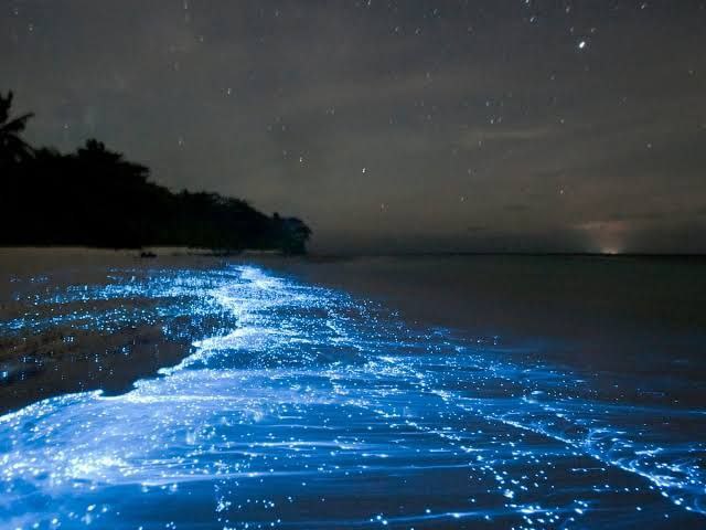
Phosphorescence is a type of photoluminescence related to fluorescence. When exposed to light (radiation) of a shorter wavelength, a phosphorescent substance will glow, absorbing the light and reemitting it at a longer wavelength. Unlike fluorescence, a phosphorescent material does not immediately reemit the radiation it absorbs. Instead, a phosphorescent material absorbs some of the radiation energy and reemits it for a much longer time after the radiation source is removed. In a general sense, there is no distinct boundary between the emission times of fluorescence and phosphorescence (i.e.: if a substance glows under a black light it is generally considered fluorescent, and if it glows in the dark it is often simply called phosphorescent). In a modern, scientific sense, the phenomena can usually be classified by the three different mechanisms that produce the light, and the typical timescales during which those mechanisms emit light. Whereas fluorescent materials stop emitting light within nanoseconds (billionths of a second) after the excitation radiation is removed, phosphorescent materials may continue to emit an afterglow ranging from a few microseconds to many hours after the excitation is removed.
━━━━━━━━━━━━
☢ @Physics ⚡| @Education 📖
━━━━━━━━━━━━
☢ @Physics ⚡| @Education 📖
👍51❤15😱14🔥11😁2🤩2😢1
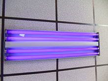
▶️ A blacklight, also called a UV-A light, Wood's lamp, or ultraviolet light, is a lamp that emits long-wave (UV-A) ultraviolet light and very little visible light.
▶️ One type of lamp has a violet filter material, either on the bulb or in a separate glass filter in the lamp housing, which blocks most visible light and allows through UV, so the lamp has a dim violet glow when operating. Blacklight lamps which have this filter have a lighting industry designation that includes the letters "BLB". This stands for "blacklight blue".
▶️ A second type of lamp produces ultraviolet but does not have the filter material, so it produces more visible light and has a blue color when operating. These tubes are made for use in "bug zapper" insect traps, and are identified by the industry designation "BL". This stands for "blacklight".
━━━━━━━━━━━━
☢ @Physics ⚡| @Education 📖
▶️ One type of lamp has a violet filter material, either on the bulb or in a separate glass filter in the lamp housing, which blocks most visible light and allows through UV, so the lamp has a dim violet glow when operating. Blacklight lamps which have this filter have a lighting industry designation that includes the letters "BLB". This stands for "blacklight blue".
▶️ A second type of lamp produces ultraviolet but does not have the filter material, so it produces more visible light and has a blue color when operating. These tubes are made for use in "bug zapper" insect traps, and are identified by the industry designation "BL". This stands for "blacklight".
━━━━━━━━━━━━
☢ @Physics ⚡| @Education 📖
🔥26👍18❤5😱5😢3
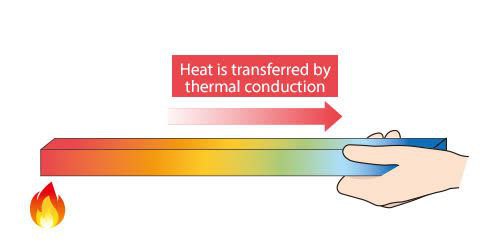
▶️ Conduction is the process by which heat is transferred from the hotter end to the colder end of an object.
▶️ Heat spontaneously flows from a hotter body to a colder body. For example, heat is conducted from the hotplate of an electric stove to the bottom of a saucepan in contact with it. In the absence of an opposing external driving energy source, within a body or between bodies, temperature differences decay over time, and thermal equilibrium is approached, temperature becoming more uniform.
▶️ In conduction, the heat flow is within and through the body itself. In contrast, in heat transfer by thermal radiation, the transfer is often between bodies, which may be separated spatially. Heat can also be transferred by a combination of conduction and radiation. In solids, conduction is mediated by the combination of vibrations and collisions of molecules, propagation and collisions of phonons, and diffusion and collisions of free electrons. In gases and liquids, conduction is due to the collisions and diffusion of molecules during their random motion. Photons in this context do not collide with one another, and so heat transport by electromagnetic radiation is conceptually distinct from heat conduction by microscopic diffusion and collisions of material particles and phonons. But the distinction is often not easily observed unless the material is semi-transparent.
━━━━━━━━━━━━
☢ @Physics ⚡| @Education 📖
▶️ Heat spontaneously flows from a hotter body to a colder body. For example, heat is conducted from the hotplate of an electric stove to the bottom of a saucepan in contact with it. In the absence of an opposing external driving energy source, within a body or between bodies, temperature differences decay over time, and thermal equilibrium is approached, temperature becoming more uniform.
▶️ In conduction, the heat flow is within and through the body itself. In contrast, in heat transfer by thermal radiation, the transfer is often between bodies, which may be separated spatially. Heat can also be transferred by a combination of conduction and radiation. In solids, conduction is mediated by the combination of vibrations and collisions of molecules, propagation and collisions of phonons, and diffusion and collisions of free electrons. In gases and liquids, conduction is due to the collisions and diffusion of molecules during their random motion. Photons in this context do not collide with one another, and so heat transport by electromagnetic radiation is conceptually distinct from heat conduction by microscopic diffusion and collisions of material particles and phonons. But the distinction is often not easily observed unless the material is semi-transparent.
━━━━━━━━━━━━
☢ @Physics ⚡| @Education 📖
🔥19👍15❤10🤩7😱3
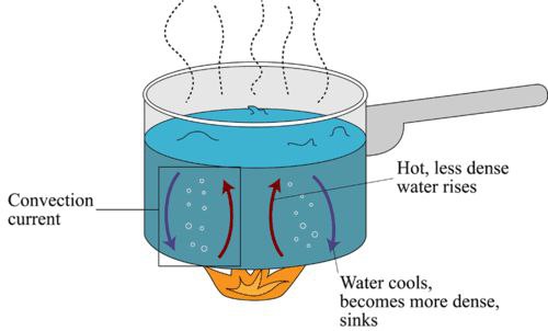
Convection (or convective heat transfer) is the transfer of heat from one place to another due to the movement of fluid. Although often discussed as a distinct method of heat transfer, convective heat transfer involves the combined processes of conduction (heat diffusion) and advection (heat transfer by bulk fluid flow). Convection is usually the dominant form of heat transfer in liquids and gases.
━━━━━━━━━━━━
☢ @Physics ⚡| @Education 📖
━━━━━━━━━━━━
☢ @Physics ⚡| @Education 📖
❤20👍19🔥13😱5
▶️ Thermal radiation is electromagnetic radiation generated by the thermal motion of particles in matter. Thermal radiation is generated when heat from the movement of charges in the material (electrons and protons in common forms of matter) is converted to electromagnetic radiation. All matter with a temperature greater than absolute zero emits thermal radiation. At room temperature, most of the emission is in the infrared (IR) spectrum. Particle motion results in charge-acceleration or dipole oscillation which produces electromagnetic radiation.
▶️ Infrared radiation emitted by animals (detectable with an infrared camera) and cosmic microwave background radiation are examples of thermal radiation.
▶️ If a radiation object meets the physical characteristics of a black body in thermodynamic equilibrium, the radiation is called blackbody radiation. Planck's law describes the spectrum of blackbody radiation, which depends solely on the object's temperature. Wien's displacement law determines the most likely frequency of the emitted radiation, and the Stefan–Boltzmann law gives the radiant intensity.
▶️ Thermal radiation is also one of the fundamental mechanisms of heat transfer.
━━━━━━━━━━━━
☢ @Physics ⚡| @Education 📖
▶️ Infrared radiation emitted by animals (detectable with an infrared camera) and cosmic microwave background radiation are examples of thermal radiation.
▶️ If a radiation object meets the physical characteristics of a black body in thermodynamic equilibrium, the radiation is called blackbody radiation. Planck's law describes the spectrum of blackbody radiation, which depends solely on the object's temperature. Wien's displacement law determines the most likely frequency of the emitted radiation, and the Stefan–Boltzmann law gives the radiant intensity.
▶️ Thermal radiation is also one of the fundamental mechanisms of heat transfer.
━━━━━━━━━━━━
☢ @Physics ⚡| @Education 📖

👍27🔥13❤9😱3😁2
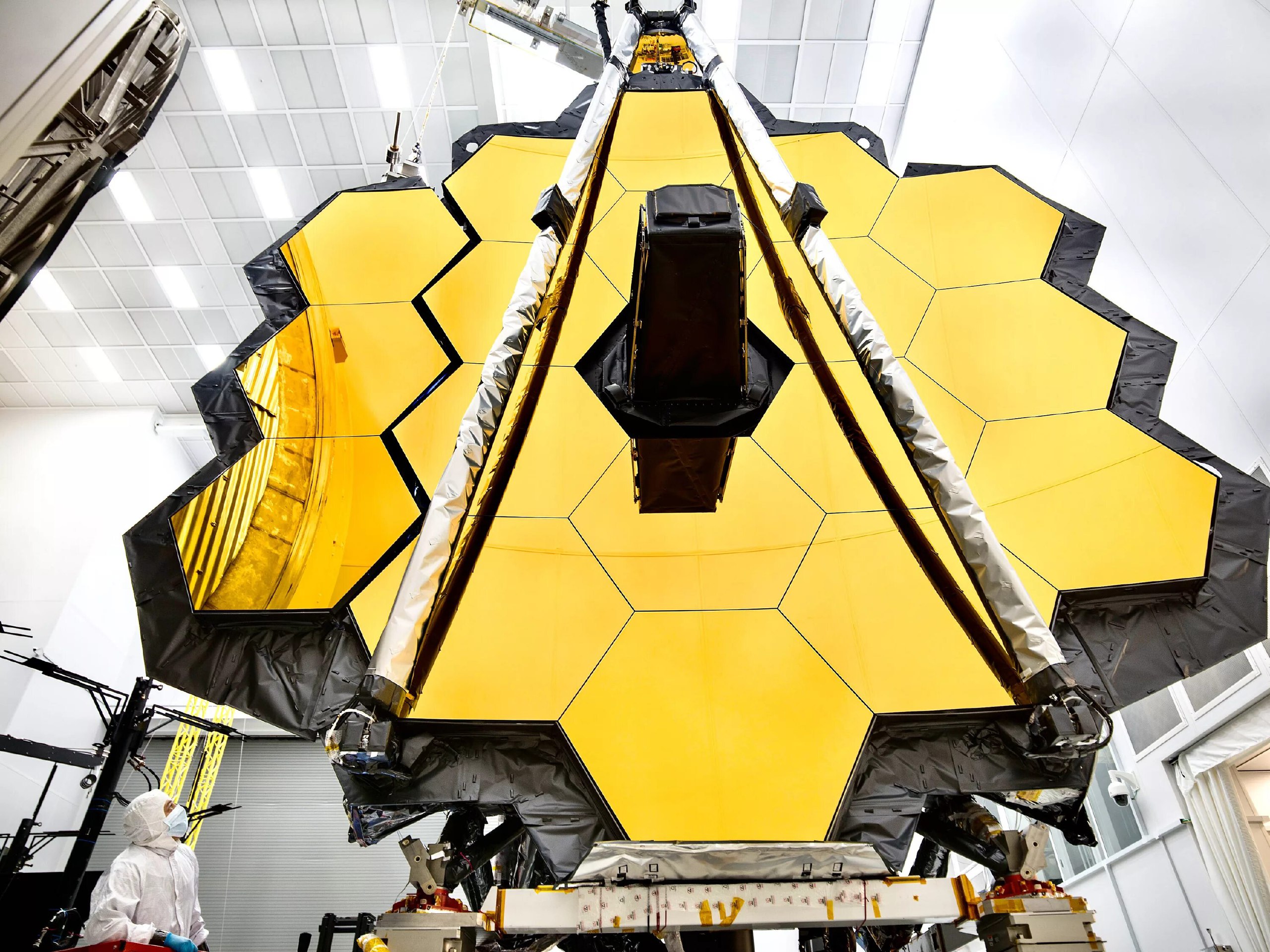
🔵 WHY ARE THE MIRRORS OF JAMES WEBB SPACE TELESCOPE (JWST) GOLDEN❓
▶️ Gold is a good infrared reflector, and JWST is designed to observe infrared light for observing the oldest galaxies in the universe. Hence, a 100 micrometre thin layer of Gold is applied to mirrors.
━━━━━━━━━━━━
☢ @Physics ⚡| @Education 📖
▶️ Gold is a good infrared reflector, and JWST is designed to observe infrared light for observing the oldest galaxies in the universe. Hence, a 100 micrometre thin layer of Gold is applied to mirrors.
━━━━━━━━━━━━
☢ @Physics ⚡| @Education 📖
🔥29👍22❤14🎉5
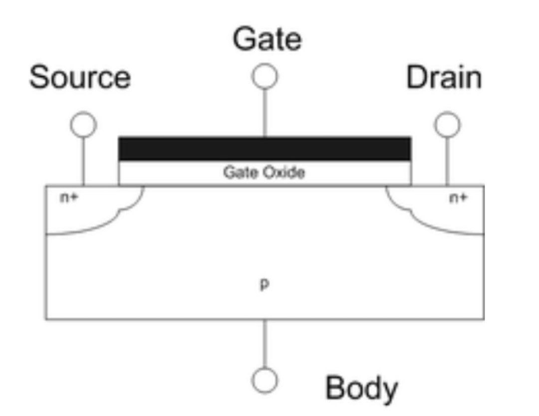
The field-effect transistor (FET) is a type of transistor that uses an electric field to control the flow of current in a semiconductor. FETs (JFETs or MOSFETs) are devices with three terminals: source, gate, and drain. FETs control the flow of current by the application of a voltage to the gate, which in turn alters the conductivity between the drain and source. FETs are also known as unipolar transistors since they involve single-carrier-type operation. That is, FETs use either electrons (n-channel) or holes (p-channel) as charge carriers in their operation, but not both. Many different types of field effect transistors exist. Field effect transistors generally display very high input impedance at low frequencies. The most widely used field-effect transistor is the MOSFET (metal-oxide-semiconductor field-effect transistor).
The image down below shows the cross-sectional view of a field-effect transistor, showing source, gate and drain terminals.
━━━━━━━━━━━━
☢ @Physics ⚡| @Education 📖
The image down below shows the cross-sectional view of a field-effect transistor, showing source, gate and drain terminals.
━━━━━━━━━━━━
☢ @Physics ⚡| @Education 📖
👍23❤11🔥7🤩3😱2🎉2