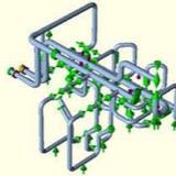
Flange analysis is done based on the Kellogg equivalent pressure method. In addition to internal and external pressure, axial force and bending moment can act on flanges as equivalent pressure. The values of axial force and bending moment are determined from analysis without pressure thrust effect.
These internal forces are used to determine the equivalent design pressure of flange pair by formula
Now enter PN into the ASME B 16.5 pressure-temperature rating table associated with flange material. If PN is less than the allowed pressure on the rating table corresponding to the associated temperature then flange will not leak. If flange leak, then reduce bending moment and axial force acting on the flange or select the greater class flange.
1) This section presents the design methodology to be used when providing thrust restraint for
buried pressurized piping. It includes guidelines for the design of thrust blocking using the
standard details and special design requirements for non-standard thrust blocks and restrained
joint pipe.
buried pressurized piping. It includes guidelines for the design of thrust blocking using the
standard details and special design requirements for non-standard thrust blocks and restrained
joint pipe.
2) For pipe sizes larger than 24-inch, consider the cost of using one of the approved restrained joints or providing concrete thrust blocking to restrain the pipe or fitting. If the cost is approximately equal, design for concrete thrust blocks and if the restrained joints are considerably less expensive, then design for restrained joints unless otherwise directed.
3) In a pressurized buried pipeline such as a water main or sewage force main, thrust forces act on the pipe where changes in fluid velocity, changes in pipe size or changes in pipeline direction occur. This is generally at fittings such as plugs, caps, valves, tees, bends or reducers.
4) Thrust forces may also occur at the locations where new pipe is connected in-line to a different type of existing pipe with different sealing diameters. A significant example of this is the connection of large diameter Prestressed Concrete Cylinder Pipe (PCCP) and Ductile Iron Pipe (DIP). A thrust force is created at this type of connection in the same manner as a reducer, see Unbalanced Thrust at Connections to Existing Water Pipelines, in this section.