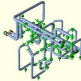
“Static” snubbers have a support restraint called SNB following a translational direction in the restraint type field. When a snubber is entered, the restraint fields in Ceasar II change as follows: Gap and Mu are disabled.
Snubbers are the translational restraints which provide resistance to displacement in static analysis of occasional loads only. It is assumed that occasional loading is dynamic in nature, similar to a static seismic or static wind loading. These snubbers are inactive for all expansion sustained, and operating static cases, and are active for all types of true dynamic analyses, i.e. harmonic, modal, or spectral. These restraints will be active in all static load cases defined as occasional in the load case list.
Static snubbers may be directional, i.e. may be preceded by a minus or plus sign. The steps for modelling Snubber are mentioned below:
• Create a node where snubber is required to add. (Node 10)
• Run the operating cases without defining a snubber at that node.
• Note the displacement in all six degrees of freedom at the location (Node 10) where to add the snubbers (Assume D1 is the displacement at that node at T1 temp and D2 at T2 temp).
• From input piping spreadsheet click on restraint check box and define XSNB/ZSNB etc as per requirement at node 10 with a distinct CNode 11. It will appear as a guide in Caesar Sketch.
• Place displacements on the CNode (CNode 11) by activating displacement checkbox.
• Modify the load cases by including D1 everywhere T1 displays and D2 where T2 appears for Operating load cases.
• For defining occasional stresses create the following load cases as given in Fig. 1.
• Run the analysis to obtain results.
Snubbers are the translational restraints which provide resistance to displacement in static analysis of occasional loads only. It is assumed that occasional loading is dynamic in nature, similar to a static seismic or static wind loading. These snubbers are inactive for all expansion sustained, and operating static cases, and are active for all types of true dynamic analyses, i.e. harmonic, modal, or spectral. These restraints will be active in all static load cases defined as occasional in the load case list.
Static snubbers may be directional, i.e. may be preceded by a minus or plus sign. The steps for modelling Snubber are mentioned below:
• Create a node where snubber is required to add. (Node 10)
• Run the operating cases without defining a snubber at that node.
• Note the displacement in all six degrees of freedom at the location (Node 10) where to add the snubbers (Assume D1 is the displacement at that node at T1 temp and D2 at T2 temp).
• From input piping spreadsheet click on restraint check box and define XSNB/ZSNB etc as per requirement at node 10 with a distinct CNode 11. It will appear as a guide in Caesar Sketch.
• Place displacements on the CNode (CNode 11) by activating displacement checkbox.
• Modify the load cases by including D1 everywhere T1 displays and D2 where T2 appears for Operating load cases.
• For defining occasional stresses create the following load cases as given in Fig. 1.
• Run the analysis to obtain results.
Application: Snubbers are normally used for reducing the damaging effects of Earthquake events.
Supporting pipe risers subject to thermal expansion and contraction in hi-rise HVAC Systems has presented tremendous problems to the Design Engineer.
Solutions for accommodating this movement include horizontal expansion loops or incorporating expansion joints and several anchor points. These methods may be adequate, but there are many negative features.
The use of horizontal expansion loops (Figure A) can result in the need for higher horse power pumps to overcome the additional friction and directional change in the horizontal runs. The additional horizontal piping adds to material and labor costs and may reduce the amount of rentable space as the pipe leaves and returns to the riser chase.
to the introduction of stainless steel or rubber expansion joints (Figure B), Design Engineers had no choice but to incorporate expansion loops and anchors. Expansion joints enabled the Engineer to keep the riser straight, but potential failure became an issue. The failure of an expansion joint means not only loss of heating or cooling, but a good possibility of extensive water or steam damage. In order to periodically inspect the expansion joints, they must remain accessible and this is not always possible. Additional valving becomes a necessity for rapid shut down or maintenance. Valves are both expensive and slow to close to avoid water damage.
Both expansion joints and expansion loop systems require multiple anchor points which present the Design Engineer with yet another difficult task. The loads on the anchor pairs can be quite high when coupled with the forces to move the expansion loops or expansion joints plus expansion joint thrust. Large safety factors become advisable for both anchorage and structural supports.
Today’s state of the art riser support design simplifies these problems by incorporating multiple spring mounts strategically placed to support the riser and allow expansion and contraction with small and easily calculable load changes. (Figure C)
The spring support systems can be designed to utilize a central isolated anchor which remains neutral during operation, or a totally free-floating system with spring support only. If a single anchor is used, it is located as close as possible to the middle of the riser to direct the pipe to expand away or contract towards the anchor point. By locating the anchor in the center of the riser the expansion and contraction at each end is cut in half. The anchor is designed to withstand the “worst case” forces generated when the water weight is removed for maintenance of equipment without the need to access and re-adjust the mountings.
Unanchored or totally free-floating systems are designed to expand or contract from the center as well, but control is far more difficult as branch off and end stiffnesses are difficult to calculate and installations must be closely watched to avoid accidental movement restrictions at branch offs. In addition, when water weight is removed for equipment maintenance, an alternate restraint method or individual mounting readjustment may be required.
Depending on the support structures strength, the number and location of spring mounts may vary from one set on every floor for maximum load distribution or they may be spaced at greater intervals. Isolated pipe guides should be used in most systems to maintain alignment of anchored or unanchored spring support systems. Risers can be butt welded when installed to assure integrity. They are easy to install and require no maintenance.
Most importantly, the load at each support point is known under all conditions, i.e., installed, empty, full and operating at both temperature extremes. An added benefit is that the riser is not only supported with minor load changes throughout its expansion and contraction, but it is also effectively isolated from the building as the springs provide low natural frequency support.
All negative aspects of the obsolete systems are avoided with properly designed spring supported riser systems.
All negative aspects of the obsolete systems are avoided with properly designed spring supported riser systems.