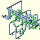
External Perturbation
In an ideal situation, pipe vibration would be non-existent if the fluid could flow through the piping system without any disturbances that would cause perturbation. However, in real-life situations, there are many sources that generate perturbation in the piping system and subsequently cause vibration
In an ideal situation, pipe vibration would be non-existent if the fluid could flow through the piping system without any disturbances that would cause perturbation. However, in real-life situations, there are many sources that generate perturbation in the piping system and subsequently cause vibration
Causes of Perturbation
Here we can separate the main causes into a few main categories:
(a) Mechanical, (b) Fluid Induced, (c) Transients
(a) Mechanical:
(i) Perturbation originating from the pump or compressor.
(ii) Mechanical perturbation propagating from other moving mechanical components.
(b) Fluid Induced:
(i) Flow turbulence (broad band spectra): Function of Reynolds number
(ii) Multiphase flow: Propagation of slugs (quasi-periodic) and their implosion/explosion may cause serious vibration.
(iii) Bends & elbows: These produce secondary flows causing further interaction and enhancing strong vertical flows of quasi-periodic nature.
(iv) Valves: Valves cause flow separation and/or direction change which leads to high intensity turbulence (Reynolds number dependent).
(c) Transients:
(i) Sudden rupture of pipe
(ii) Sudden closure of valve
(iii) External forces on the pipe or piping components
Here we can separate the main causes into a few main categories:
(a) Mechanical, (b) Fluid Induced, (c) Transients
(a) Mechanical:
(i) Perturbation originating from the pump or compressor.
(ii) Mechanical perturbation propagating from other moving mechanical components.
(b) Fluid Induced:
(i) Flow turbulence (broad band spectra): Function of Reynolds number
(ii) Multiphase flow: Propagation of slugs (quasi-periodic) and their implosion/explosion may cause serious vibration.
(iii) Bends & elbows: These produce secondary flows causing further interaction and enhancing strong vertical flows of quasi-periodic nature.
(iv) Valves: Valves cause flow separation and/or direction change which leads to high intensity turbulence (Reynolds number dependent).
(c) Transients:
(i) Sudden rupture of pipe
(ii) Sudden closure of valve
(iii) External forces on the pipe or piping components
Causes of Perturbation:
Thorough plant design should ensure that the Eigen-modes and Eigen-values of the overall system subjected to external perturbations should not match those of the piping system when subjected to those same external perturbations. Low frequency, long waves will cause immediate problems; whereas high frequency, low amplitude vibrations will cause fatigue failures over time. Therefore, one must be careful in designing the piping system and should use various vibration mitigating devices placed at proper locations. In addition, proper process controls should be used to reduce vibration especially in multiphase flows.
Thorough plant design should ensure that the Eigen-modes and Eigen-values of the overall system subjected to external perturbations should not match those of the piping system when subjected to those same external perturbations. Low frequency, long waves will cause immediate problems; whereas high frequency, low amplitude vibrations will cause fatigue failures over time. Therefore, one must be careful in designing the piping system and should use various vibration mitigating devices placed at proper locations. In addition, proper process controls should be used to reduce vibration especially in multiphase flows.
Co-Efficient of Friction for pipe supporting during Stress Analysis using Caesar II
All piping stress engineers must be aware that while modeling supports or restraints in Caesar II input spreadsheet we have to enter the frictional co-efficient. The value of this co-efficient depends on the supporting surface material and surface roughness. During project bidding stage (ITB Document) the client generally provides the information regarding which friction factor to be used for which surface. Also every EPC organization prepares their own guideline for using standard friction factor in case not available in ITB document. The following write up will try to provide an idea regarding which co-efficient of friction to be used in what situation. This can be used as a guide only. However project specific data or information will override any word mentioned here.
• Coefficient of friction factor depending upon the supporting interface (i.e, junction between Top of Steel and Bottom of Pipe or Bottom of Shoe/Cradle) shall be applied at all vertical restraint (+Y or Y supports) locations as mentioned below. But if ITB for any project provides separate data then those data shall be considered.
o Carbon Steel to Carbon Steel: 0.3
o Polished Stainless Steel to Polished Stainless Steel/Graphite: 0.15
o Teflon to Teflon/ Polished Stainless Steel: 0.10
o Concrete to Carbon Steel: 0.4
o Pipe to Roll Support: 0.01
o Teflon to Carbon Steel: 0.2
• There is various philosophy among EPC companies regarding the use of co-efficient of friction for guide and directional anchor supports. Some organization prefer not to use any frictional co-efficient for horizontal supports. However if used the same can be taken from the above table (normally 0.3 is used if no special arrangement is made).
• No friction factor to be used while supporting using rigid hangers.
• In case when Sliding Plate is required, put the comment as “(PTFE/Graphite) Sliding Plate Required” and mention friction factor μ=0.1 /0.15 respectively depending on temperature” on stress sketch. Use Teflon (PTFE) Slide plate up to a Temp of 204 degree Centigrade, above which use graphite plate (up to 540 degree Centigrade).
• Normally the friction factor shall not be applied when modeling bottom type spring. But sometimes ITB document/Client could insist for friction modeling of bottom type springs, in that situation friction factor could be applied as per requirement.
• When the pipe/shoe is supported on the welded rod on the structure then friction factor of 0.25 shall be considered.
• Coefficient of friction factor depending upon the supporting interface (i.e, junction between Top of Steel and Bottom of Pipe or Bottom of Shoe/Cradle) shall be applied at all vertical restraint (+Y or Y supports) locations as mentioned below. But if ITB for any project provides separate data then those data shall be considered.
o Carbon Steel to Carbon Steel: 0.3
o Polished Stainless Steel to Polished Stainless Steel/Graphite: 0.15
o Teflon to Teflon/ Polished Stainless Steel: 0.10
o Concrete to Carbon Steel: 0.4
o Pipe to Roll Support: 0.01
o Teflon to Carbon Steel: 0.2
• There is various philosophy among EPC companies regarding the use of co-efficient of friction for guide and directional anchor supports. Some organization prefer not to use any frictional co-efficient for horizontal supports. However if used the same can be taken from the above table (normally 0.3 is used if no special arrangement is made).
• No friction factor to be used while supporting using rigid hangers.
• In case when Sliding Plate is required, put the comment as “(PTFE/Graphite) Sliding Plate Required” and mention friction factor μ=0.1 /0.15 respectively depending on temperature” on stress sketch. Use Teflon (PTFE) Slide plate up to a Temp of 204 degree Centigrade, above which use graphite plate (up to 540 degree Centigrade).
• Normally the friction factor shall not be applied when modeling bottom type spring. But sometimes ITB document/Client could insist for friction modeling of bottom type springs, in that situation friction factor could be applied as per requirement.
• When the pipe/shoe is supported on the welded rod on the structure then friction factor of 0.25 shall be considered.
In this article I will explain the step by step procedure for modelling Snubber in Caesar II.
“Static” snubbers have a support restraint called SNB following a translational direction in the restraint type field. When a snubber is entered, the restraint fields in Ceasar II change as follows: Gap and Mu are disabled.
Snubbers are the translational restraints which provide resistance to displacement in static analysis of occasional loads only. It is assumed that occasional loading is dynamic in nature, similar to a static seismic or static wind loading. These snubbers are inactive for all expansion sustained, and operating static cases, and are active for all types of true dynamic analyses, i.e. harmonic, modal, or spectral. These restraints will be active in all static load cases defined as occasional in the load case list.
Static snubbers may be directional, i.e. may be preceded by a minus or plus sign. The steps for modelling Snubber are mentioned below:
• Create a node where snubber is required to add. (Node 10)
• Run the operating cases without defining a snubber at that node.
• Note the displacement in all six degrees of freedom at the location (Node 10) where to add the snubbers (Assume D1 is the displacement at that node at T1 temp and D2 at T2 temp).
• From input piping spreadsheet click on restraint check box and define XSNB/ZSNB etc as per requirement at node 10 with a distinct CNode 11. It will appear as a guide in Caesar Sketch.
• Place displacements on the CNode (CNode 11) by activating displacement checkbox.
• Modify the load cases by including D1 everywhere T1 displays and D2 where T2 appears for Operating load cases.
• For defining occasional stresses create the following load cases as given in Fig. 1.
• Run the analysis to obtain results.
Snubbers are the translational restraints which provide resistance to displacement in static analysis of occasional loads only. It is assumed that occasional loading is dynamic in nature, similar to a static seismic or static wind loading. These snubbers are inactive for all expansion sustained, and operating static cases, and are active for all types of true dynamic analyses, i.e. harmonic, modal, or spectral. These restraints will be active in all static load cases defined as occasional in the load case list.
Static snubbers may be directional, i.e. may be preceded by a minus or plus sign. The steps for modelling Snubber are mentioned below:
• Create a node where snubber is required to add. (Node 10)
• Run the operating cases without defining a snubber at that node.
• Note the displacement in all six degrees of freedom at the location (Node 10) where to add the snubbers (Assume D1 is the displacement at that node at T1 temp and D2 at T2 temp).
• From input piping spreadsheet click on restraint check box and define XSNB/ZSNB etc as per requirement at node 10 with a distinct CNode 11. It will appear as a guide in Caesar Sketch.
• Place displacements on the CNode (CNode 11) by activating displacement checkbox.
• Modify the load cases by including D1 everywhere T1 displays and D2 where T2 appears for Operating load cases.
• For defining occasional stresses create the following load cases as given in Fig. 1.
• Run the analysis to obtain results.
Application: Snubbers are normally used for reducing the damaging effects of Earthquake events.
Supporting pipe risers subject to thermal expansion and contraction in hi-rise HVAC Systems has presented tremendous problems to the Design Engineer.
Solutions for accommodating this movement include horizontal expansion loops or incorporating expansion joints and several anchor points. These methods may be adequate, but there are many negative features.
The use of horizontal expansion loops (Figure A) can result in the need for higher horse power pumps to overcome the additional friction and directional change in the horizontal runs. The additional horizontal piping adds to material and labor costs and may reduce the amount of rentable space as the pipe leaves and returns to the riser chase.
to the introduction of stainless steel or rubber expansion joints (Figure B), Design Engineers had no choice but to incorporate expansion loops and anchors. Expansion joints enabled the Engineer to keep the riser straight, but potential failure became an issue. The failure of an expansion joint means not only loss of heating or cooling, but a good possibility of extensive water or steam damage. In order to periodically inspect the expansion joints, they must remain accessible and this is not always possible. Additional valving becomes a necessity for rapid shut down or maintenance. Valves are both expensive and slow to close to avoid water damage.
Both expansion joints and expansion loop systems require multiple anchor points which present the Design Engineer with yet another difficult task. The loads on the anchor pairs can be quite high when coupled with the forces to move the expansion loops or expansion joints plus expansion joint thrust. Large safety factors become advisable for both anchorage and structural supports.
Today’s state of the art riser support design simplifies these problems by incorporating multiple spring mounts strategically placed to support the riser and allow expansion and contraction with small and easily calculable load changes. (Figure C)