Forwarded from Piping Stress Analysis (PSA Group)
2- Rotation of Shell
The unrestrained rotation of the shell at the centre of the nozzle-shell connection resulting from product head shall be determined as follows:
The unrestrained rotation of the shell at the centre of the nozzle-shell connection resulting from product head shall be determined as follows:
Forwarded from Piping Stress Analysis (PSA Group)
The allowable Nozzle load can be calculated as per Appendix P- (p.2.7) or the allowable loads can be used which will be furnished by Vendor/ Mechanical Static.
Forwarded from Piping Stress Analysis (PSA Group)
SUPPORTING OF LINES CONNECTED TO TANK
Forwarded from Piping Stress Analysis (PSA Group)
Note:
1. In desert conditions Hanger type springs is used to prevent malfunctioning of Spring due to the accumulation of sand particles
2. for Large diameter tanks, tank bulging plays a important role in nozzle loading and support selection . Spring support can be advised .
1. In desert conditions Hanger type springs is used to prevent malfunctioning of Spring due to the accumulation of sand particles
2. for Large diameter tanks, tank bulging plays a important role in nozzle loading and support selection . Spring support can be advised .
Methods for flange leakage checking by Pressure Equivalent Method using Caesar II
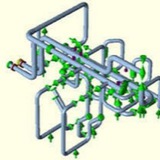
• Model the stress system from stress isometric. After modelling is complete select the flange which needs checking as per pressure equivalent method. In Fig. 1, node 20-30 and node 30-40 denotes the flange assembly. And flange leakage checking is required for node 30.
• Now select the Flange Node(From/To/Both) and Calculation Type as shown in Fig. 2.
• Select Flange Class/Grade through ‘Read from File’ button and refer to ASME B 16.5/ ASME B 16.47 material tables.
• Required data will automatically be filled. By default the value of G will be taken as the mean gasket diameter. User to update the value of G as per ASME B 16.20 & ASME Sec. VIII Div. 1, Appendix 2, Table 2-5-2. based on following equation:
o b0 = 1/4, G = Mean diameter of the gasket contact face
o b0 > 1/4, G = Outside diameter of gasket contact face less 2b, b=basic gasket width from code. check the above mentioned link for details.
• Now select the Flange Node(From/To/Both) and Calculation Type as shown in Fig. 2.
• Select Flange Class/Grade through ‘Read from File’ button and refer to ASME B 16.5/ ASME B 16.47 material tables.
• Required data will automatically be filled. By default the value of G will be taken as the mean gasket diameter. User to update the value of G as per ASME B 16.20 & ASME Sec. VIII Div. 1, Appendix 2, Table 2-5-2. based on following equation:
o b0 = 1/4, G = Mean diameter of the gasket contact face
o b0 > 1/4, G = Outside diameter of gasket contact face less 2b, b=basic gasket width from code. check the above mentioned link for details.
• Now go to the load case editor and select the temperature at which flange leakage checking to be performed as shown in Fig. 3. Now run the analysis to check the results. In case the generated stress exceeds the allowable results will be shown in red color. Check Fig. 4 for output results.