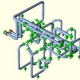
2. Pipe Rack Loading:
Rack loading is provided to CSA for economic designing of the pipe rack. Providing pipe rack loading is a very difficult task for a stress engineer as most of the organizations does not have any guidelines. Normally Pipe rack loads are transferred in 3 stages:
a. Initial rack loading for rack foundation design (before piling): Project has just started and very less data is available. Piping design places the lines over the rack based on preliminary P&ID. Rack loads are provided mostly based on assumption/experience. Conservative loads are to be provided.
b. Rack loading for member sizing (after 30% model review): Most of the data has started arriving. Loads to be provided based on actual analysis.
c. Rack loading for final member checking (after 60% model review): All vendors are decided. Line size and locations are finalized. All critical lines are fixed. Loads are provided for checking designed members again. Loads to be provided based on Software analysis.
Few points to keep in mind while providing Rack loading:
1. Operating, Water filled and Occasional loads for big size lines (>16 inch NPS) to be provided separately. For guides and anchors loads with and without friction should be provided.
2. For Flare line 1/3rd water filled weight can be considered.
3. Proper directions to be marked.
4. After a long run don’t provide guide in the immediate first possible location after bend.
5. Consider concentrated loads of inline valves, flanges, equipments etc.
6. Sometimes large equipments are placed over the pipe racks (Air Fin Fan Cooler, Heat Exchangers etc). So take operating weight of equipments from mechanical group.
7. Cable tray loads are to be taken from electrical/instrumentation group. (In absence of data a uniformly distributed load of 1.0 KPa for single level and 1.9 KPa for double level of cable trays can be considered)
8. Include the forces of PSV reactions if applicable.
In absence of data following guidelines can be used as preliminary piping loads:
a. A uniformly distributed load of 1.9KPa for piping, product and insulation can be considered for line size (for each line)
b. For line size larger than 12 inch nominal diameter actual concentrated load including the weight of piping, product, valves, fittings and insulation shall be used.
Rack loading is provided to CSA for economic designing of the pipe rack. Providing pipe rack loading is a very difficult task for a stress engineer as most of the organizations does not have any guidelines. Normally Pipe rack loads are transferred in 3 stages:
a. Initial rack loading for rack foundation design (before piling): Project has just started and very less data is available. Piping design places the lines over the rack based on preliminary P&ID. Rack loads are provided mostly based on assumption/experience. Conservative loads are to be provided.
b. Rack loading for member sizing (after 30% model review): Most of the data has started arriving. Loads to be provided based on actual analysis.
c. Rack loading for final member checking (after 60% model review): All vendors are decided. Line size and locations are finalized. All critical lines are fixed. Loads are provided for checking designed members again. Loads to be provided based on Software analysis.
Few points to keep in mind while providing Rack loading:
1. Operating, Water filled and Occasional loads for big size lines (>16 inch NPS) to be provided separately. For guides and anchors loads with and without friction should be provided.
2. For Flare line 1/3rd water filled weight can be considered.
3. Proper directions to be marked.
4. After a long run don’t provide guide in the immediate first possible location after bend.
5. Consider concentrated loads of inline valves, flanges, equipments etc.
6. Sometimes large equipments are placed over the pipe racks (Air Fin Fan Cooler, Heat Exchangers etc). So take operating weight of equipments from mechanical group.
7. Cable tray loads are to be taken from electrical/instrumentation group. (In absence of data a uniformly distributed load of 1.0 KPa for single level and 1.9 KPa for double level of cable trays can be considered)
8. Include the forces of PSV reactions if applicable.
In absence of data following guidelines can be used as preliminary piping loads:
a. A uniformly distributed load of 1.9KPa for piping, product and insulation can be considered for line size (for each line)
b. For line size larger than 12 inch nominal diameter actual concentrated load including the weight of piping, product, valves, fittings and insulation shall be used.
All piping systems typically used in industrial application are made of elastic material. Elastic materials vibrate even under small perturbations due to their elastic properties. Since solid materials have a non-zero stiffness factor for both volumetric and shear deformations, these perturbations can generate waves with different velocities depending upon the deformation mode. Volumetric perturbations produce transverse waves while shear perturbations produce longitudinal waves.
External Perturbation
In an ideal situation, pipe vibration would be non-existent if the fluid could flow through the piping system without any disturbances that would cause perturbation. However, in real-life situations, there are many sources that generate perturbation in the piping system and subsequently cause vibration
In an ideal situation, pipe vibration would be non-existent if the fluid could flow through the piping system without any disturbances that would cause perturbation. However, in real-life situations, there are many sources that generate perturbation in the piping system and subsequently cause vibration
Causes of Perturbation
Here we can separate the main causes into a few main categories:
(a) Mechanical, (b) Fluid Induced, (c) Transients
(a) Mechanical:
(i) Perturbation originating from the pump or compressor.
(ii) Mechanical perturbation propagating from other moving mechanical components.
(b) Fluid Induced:
(i) Flow turbulence (broad band spectra): Function of Reynolds number
(ii) Multiphase flow: Propagation of slugs (quasi-periodic) and their implosion/explosion may cause serious vibration.
(iii) Bends & elbows: These produce secondary flows causing further interaction and enhancing strong vertical flows of quasi-periodic nature.
(iv) Valves: Valves cause flow separation and/or direction change which leads to high intensity turbulence (Reynolds number dependent).
(c) Transients:
(i) Sudden rupture of pipe
(ii) Sudden closure of valve
(iii) External forces on the pipe or piping components
Here we can separate the main causes into a few main categories:
(a) Mechanical, (b) Fluid Induced, (c) Transients
(a) Mechanical:
(i) Perturbation originating from the pump or compressor.
(ii) Mechanical perturbation propagating from other moving mechanical components.
(b) Fluid Induced:
(i) Flow turbulence (broad band spectra): Function of Reynolds number
(ii) Multiphase flow: Propagation of slugs (quasi-periodic) and their implosion/explosion may cause serious vibration.
(iii) Bends & elbows: These produce secondary flows causing further interaction and enhancing strong vertical flows of quasi-periodic nature.
(iv) Valves: Valves cause flow separation and/or direction change which leads to high intensity turbulence (Reynolds number dependent).
(c) Transients:
(i) Sudden rupture of pipe
(ii) Sudden closure of valve
(iii) External forces on the pipe or piping components
Causes of Perturbation:
Thorough plant design should ensure that the Eigen-modes and Eigen-values of the overall system subjected to external perturbations should not match those of the piping system when subjected to those same external perturbations. Low frequency, long waves will cause immediate problems; whereas high frequency, low amplitude vibrations will cause fatigue failures over time. Therefore, one must be careful in designing the piping system and should use various vibration mitigating devices placed at proper locations. In addition, proper process controls should be used to reduce vibration especially in multiphase flows.
Thorough plant design should ensure that the Eigen-modes and Eigen-values of the overall system subjected to external perturbations should not match those of the piping system when subjected to those same external perturbations. Low frequency, long waves will cause immediate problems; whereas high frequency, low amplitude vibrations will cause fatigue failures over time. Therefore, one must be careful in designing the piping system and should use various vibration mitigating devices placed at proper locations. In addition, proper process controls should be used to reduce vibration especially in multiphase flows.
Co-Efficient of Friction for pipe supporting during Stress Analysis using Caesar II
All piping stress engineers must be aware that while modeling supports or restraints in Caesar II input spreadsheet we have to enter the frictional co-efficient. The value of this co-efficient depends on the supporting surface material and surface roughness. During project bidding stage (ITB Document) the client generally provides the information regarding which friction factor to be used for which surface. Also every EPC organization prepares their own guideline for using standard friction factor in case not available in ITB document. The following write up will try to provide an idea regarding which co-efficient of friction to be used in what situation. This can be used as a guide only. However project specific data or information will override any word mentioned here.
• Coefficient of friction factor depending upon the supporting interface (i.e, junction between Top of Steel and Bottom of Pipe or Bottom of Shoe/Cradle) shall be applied at all vertical restraint (+Y or Y supports) locations as mentioned below. But if ITB for any project provides separate data then those data shall be considered.
o Carbon Steel to Carbon Steel: 0.3
o Polished Stainless Steel to Polished Stainless Steel/Graphite: 0.15
o Teflon to Teflon/ Polished Stainless Steel: 0.10
o Concrete to Carbon Steel: 0.4
o Pipe to Roll Support: 0.01
o Teflon to Carbon Steel: 0.2
• There is various philosophy among EPC companies regarding the use of co-efficient of friction for guide and directional anchor supports. Some organization prefer not to use any frictional co-efficient for horizontal supports. However if used the same can be taken from the above table (normally 0.3 is used if no special arrangement is made).
• No friction factor to be used while supporting using rigid hangers.
• In case when Sliding Plate is required, put the comment as “(PTFE/Graphite) Sliding Plate Required” and mention friction factor μ=0.1 /0.15 respectively depending on temperature” on stress sketch. Use Teflon (PTFE) Slide plate up to a Temp of 204 degree Centigrade, above which use graphite plate (up to 540 degree Centigrade).
• Normally the friction factor shall not be applied when modeling bottom type spring. But sometimes ITB document/Client could insist for friction modeling of bottom type springs, in that situation friction factor could be applied as per requirement.
• When the pipe/shoe is supported on the welded rod on the structure then friction factor of 0.25 shall be considered.
• Coefficient of friction factor depending upon the supporting interface (i.e, junction between Top of Steel and Bottom of Pipe or Bottom of Shoe/Cradle) shall be applied at all vertical restraint (+Y or Y supports) locations as mentioned below. But if ITB for any project provides separate data then those data shall be considered.
o Carbon Steel to Carbon Steel: 0.3
o Polished Stainless Steel to Polished Stainless Steel/Graphite: 0.15
o Teflon to Teflon/ Polished Stainless Steel: 0.10
o Concrete to Carbon Steel: 0.4
o Pipe to Roll Support: 0.01
o Teflon to Carbon Steel: 0.2
• There is various philosophy among EPC companies regarding the use of co-efficient of friction for guide and directional anchor supports. Some organization prefer not to use any frictional co-efficient for horizontal supports. However if used the same can be taken from the above table (normally 0.3 is used if no special arrangement is made).
• No friction factor to be used while supporting using rigid hangers.
• In case when Sliding Plate is required, put the comment as “(PTFE/Graphite) Sliding Plate Required” and mention friction factor μ=0.1 /0.15 respectively depending on temperature” on stress sketch. Use Teflon (PTFE) Slide plate up to a Temp of 204 degree Centigrade, above which use graphite plate (up to 540 degree Centigrade).
• Normally the friction factor shall not be applied when modeling bottom type spring. But sometimes ITB document/Client could insist for friction modeling of bottom type springs, in that situation friction factor could be applied as per requirement.
• When the pipe/shoe is supported on the welded rod on the structure then friction factor of 0.25 shall be considered.
In this article I will explain the step by step procedure for modelling Snubber in Caesar II.
“Static” snubbers have a support restraint called SNB following a translational direction in the restraint type field. When a snubber is entered, the restraint fields in Ceasar II change as follows: Gap and Mu are disabled.
Snubbers are the translational restraints which provide resistance to displacement in static analysis of occasional loads only. It is assumed that occasional loading is dynamic in nature, similar to a static seismic or static wind loading. These snubbers are inactive for all expansion sustained, and operating static cases, and are active for all types of true dynamic analyses, i.e. harmonic, modal, or spectral. These restraints will be active in all static load cases defined as occasional in the load case list.
Static snubbers may be directional, i.e. may be preceded by a minus or plus sign. The steps for modelling Snubber are mentioned below:
• Create a node where snubber is required to add. (Node 10)
• Run the operating cases without defining a snubber at that node.
• Note the displacement in all six degrees of freedom at the location (Node 10) where to add the snubbers (Assume D1 is the displacement at that node at T1 temp and D2 at T2 temp).
• From input piping spreadsheet click on restraint check box and define XSNB/ZSNB etc as per requirement at node 10 with a distinct CNode 11. It will appear as a guide in Caesar Sketch.
• Place displacements on the CNode (CNode 11) by activating displacement checkbox.
• Modify the load cases by including D1 everywhere T1 displays and D2 where T2 appears for Operating load cases.
• For defining occasional stresses create the following load cases as given in Fig. 1.
• Run the analysis to obtain results.
Snubbers are the translational restraints which provide resistance to displacement in static analysis of occasional loads only. It is assumed that occasional loading is dynamic in nature, similar to a static seismic or static wind loading. These snubbers are inactive for all expansion sustained, and operating static cases, and are active for all types of true dynamic analyses, i.e. harmonic, modal, or spectral. These restraints will be active in all static load cases defined as occasional in the load case list.
Static snubbers may be directional, i.e. may be preceded by a minus or plus sign. The steps for modelling Snubber are mentioned below:
• Create a node where snubber is required to add. (Node 10)
• Run the operating cases without defining a snubber at that node.
• Note the displacement in all six degrees of freedom at the location (Node 10) where to add the snubbers (Assume D1 is the displacement at that node at T1 temp and D2 at T2 temp).
• From input piping spreadsheet click on restraint check box and define XSNB/ZSNB etc as per requirement at node 10 with a distinct CNode 11. It will appear as a guide in Caesar Sketch.
• Place displacements on the CNode (CNode 11) by activating displacement checkbox.
• Modify the load cases by including D1 everywhere T1 displays and D2 where T2 appears for Operating load cases.
• For defining occasional stresses create the following load cases as given in Fig. 1.
• Run the analysis to obtain results.
Application: Snubbers are normally used for reducing the damaging effects of Earthquake events.