It’s obvious from these figures von misses stress in the bottom of pipeline more than upper of pipeline. Von misses’ stress for bottom path of pipelines in depth of 2 m from ground surface is 34 MPa and for the upper path is 20 MPa also for bottom path of pipelines in depth of 4 m from ground surface is 74 MPa and for the upper path is 35 Mpa.
All plots in upper figures have showed stress on pipeline is less than yield stress of gray cast (230 MPa), so there is no plastic strain and plastic deformation.
Water hammer (or, more generally, fluid hammer) is a pressure surge or wave caused when a fluid (usually a liquid but sometimes also a gas) in motion is forced to stop or change direction suddenly (momentum change). A water hammer commonly occurs when a valve closes suddenly at an end of a pipeline system, and a pressure wave propagates in the pipe. It is also called hydraulic shock. This pressure wave can cause major problems, from noise and vibration to pipe collapse. It is possible to reduce the effects of the water hammer pulses with accumulators, expansion tanks and other features.
Damage of Water Hammer
1) Raised pressure in the pipeline causes break of facilities such as pumps, valves, pipes, and supporting structures.
2) Vapor cavities causes collapse and heavy shock wave generated in the course of column separation and subsequent causes break of the pipeline.
3) Low pressure in water supply pipeline causes health risk by letting in pollutants from outside.
4) Water hammer may cause vibration and noise or make automatic control hard due to abnormal pressure wave.
1) Raised pressure in the pipeline causes break of facilities such as pumps, valves, pipes, and supporting structures.
2) Vapor cavities causes collapse and heavy shock wave generated in the course of column separation and subsequent causes break of the pipeline.
3) Low pressure in water supply pipeline causes health risk by letting in pollutants from outside.
4) Water hammer may cause vibration and noise or make automatic control hard due to abnormal pressure wave.
Piping Flexibility Analysis and the Development of PCS – Pipe Calculation System for FEA
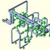
The current framework for piping stress analysis is based on a simplified calculation method directly derived from experimental research performed over 60 years ago in the 1940s and 1950s. This framework was originally intended for hand calculations and, apart from minor changes and amendments, has been successfully employed by piping engineers since its development. As computational power increases and finite element analysis (FEA) becomes accessible for piping engineers, it has become clear that this framework is not well suited for complex FEA evaluation of piping. Advanced FEA procedures enable engineers to perform in depth evaluation of piping systems that are extremely difficult or even impossible to evaluate through traditional methods. Contrasting to traditional methods, a FEA simulation allow engineers to evaluate creep-fatigue interactions, advanced material models, complex loadings, complex geometries, complex support conditions, as well as the inherent evaluation of fatigue stress intensification factors. A major difficulty for performing piping FEA simulation is that currently there are no high performance FEA packages capable of efficiently generating the required analysis model for complex piping systems.