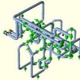
• Now you are set for analysis, so click on the run button similar to what you do for static analysis. The analysis will extract all the natural frequencies which the piping system will experience below your cut off frequency values. Fig. 5 shows such a typical modal run screen.
• After analysis run is complete the output screen will open. Select Natural frequencies to check the extracted natural frequencies of the system. Most of the time we check the animation view to get a feel of the actual vibration process. So select Natural frequencies and then click on animation button as shown in Fig. 6.
• In the animation view check how the system is experiencing vibration. Accordingly provide supporting. Normally guide and line stop supports with zero gaps will be required to arrest the vibration frequencies. Accordingly provide supporting. Sometimes hold down supports will be required.
• As soon as you will provide guide and line stop supports the system will become more rigid and expansion stresses will increase. So each time you change some support type you have to perform static analysis and make the system safe from all consideration and then proceed to dynamic module.
• As soon as you will provide guide and line stop supports the system will become more rigid and expansion stresses will increase. So each time you change some support type you have to perform static analysis and make the system safe from all consideration and then proceed to dynamic module.
Supporting of Piping Systems Few Guidelines.pdf
48.5 KB
Supporting of Piping Systems Few Guidelines
Pipe Stress Analysis Procedure:
Piping Stress Analysis in a typical engineering project is carried out using softwares like CAESAR II. The procedure adopted normally is as follows :
Piping Stress Analysis in a typical engineering project is carried out using softwares like CAESAR II. The procedure adopted normally is as follows :
1- Based on stress design criteria, stress engineer prepares stress critical lines list.
2- Stress Engineer gives it to layout engineer.
3- Layout engineer makes sure that lines are routed in 3D Model assuring enough supporting structure is available for the line.
4- Layout engineer marks logical supports on line in 3d Model at all locations where it is possible to provide a support.
5- Layout engineer then extracts isometrics, check it routing point of view with all components placed as per PID.
6- He then issues isometrics to stress engineer.
7- Layout engineer keeps track of isometrics issued to stress in a copy of stress critical lines list by adding extra columns to track stress progress.
8- Stress engineer marks node numbers on stress isometrics.
9- Stress Engineer then inputs the line data in CAESAR using classic piping input spreadsheet of CAESAR II.
10- Stress Engineer adds preliminary supports based on judgement and experience.
11- Stress Engineer then runs the static analysis.
12- Stress Engineer then checks the stress reports for :
12-1- Excessive displacements.
12-2- Nodes exceeding allowable stresses.
12-3- Excessive loads in equipment nozzles.
12-4- Excessive loads on dynamic equipments like pumps, compressors, turbines etc.
13- If stress engineer finds everything ok, he finalises supports and give back a copy of stress isometrics with support markup to layout engineer to incorporate those supports in 3d Model.
2- Stress Engineer gives it to layout engineer.
3- Layout engineer makes sure that lines are routed in 3D Model assuring enough supporting structure is available for the line.
4- Layout engineer marks logical supports on line in 3d Model at all locations where it is possible to provide a support.
5- Layout engineer then extracts isometrics, check it routing point of view with all components placed as per PID.
6- He then issues isometrics to stress engineer.
7- Layout engineer keeps track of isometrics issued to stress in a copy of stress critical lines list by adding extra columns to track stress progress.
8- Stress engineer marks node numbers on stress isometrics.
9- Stress Engineer then inputs the line data in CAESAR using classic piping input spreadsheet of CAESAR II.
10- Stress Engineer adds preliminary supports based on judgement and experience.
11- Stress Engineer then runs the static analysis.
12- Stress Engineer then checks the stress reports for :
12-1- Excessive displacements.
12-2- Nodes exceeding allowable stresses.
12-3- Excessive loads in equipment nozzles.
12-4- Excessive loads on dynamic equipments like pumps, compressors, turbines etc.
13- If stress engineer finds everything ok, he finalises supports and give back a copy of stress isometrics with support markup to layout engineer to incorporate those supports in 3d Model.
In this study, finite element models of the pipeline and soil are established using the package ABAQUS to carry out stress analysis of buried pipeline caused by static and seismic loads. In order to perform this analysis for a buried gray cast pipeline, it is necessary to accept three basic assumptions as below.
1- The welding between pipeline segments is not considered.
2- The soil is elasto-plastic characterized by Mohr Coulomb theory and the pipeline is isotropic, elastic and perfectly plastic.
3- Pipeline and soil are fully bonded each other and the interface between pipeline and soil is perfect without defects.
1- The welding between pipeline segments is not considered.
2- The soil is elasto-plastic characterized by Mohr Coulomb theory and the pipeline is isotropic, elastic and perfectly plastic.
3- Pipeline and soil are fully bonded each other and the interface between pipeline and soil is perfect without defects.
Boundary condition:
For this study, assumed infinite length for buried pipeline. It is acceptable to consider roller
as the boundary of the ends of pipeline because the buried pipeline may be moved with soil
relatively.
Additionally, the bottom surface of 3D-FE soil model is proposed to be completely fixed This
is because the bottom boundary is selected at the known location of a bedrock surface.
For this study, assumed infinite length for buried pipeline. It is acceptable to consider roller
as the boundary of the ends of pipeline because the buried pipeline may be moved with soil
relatively.
Additionally, the bottom surface of 3D-FE soil model is proposed to be completely fixed This
is because the bottom boundary is selected at the known location of a bedrock surface.