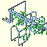
Stress Criticality and Analysis Methods:
• Highly Critical Lines (Steam turbine, Compressor connected pipelines): By Computer Analysis
• Moderately Critical Lines (AFC connected lines): By Computer Analysis
• Low critical Lines : Visual/Simple Manual Calculation/Computer analysis and
• Non Critical Lines: Visual Inspection
• Highly Critical Lines (Steam turbine, Compressor connected pipelines): By Computer Analysis
• Moderately Critical Lines (AFC connected lines): By Computer Analysis
• Low critical Lines : Visual/Simple Manual Calculation/Computer analysis and
• Non Critical Lines: Visual Inspection
Inputs:
• Stress Isometric from Layout Group
• LDT And P&ID from Process
• Equipment GA and Other detailed drawings from Mechanical
• Process flow diagram/datasheet if required from process
• Piping Material Specification
• PSV/ Control Valve GA and Datasheet from Instrumentation
• Soil Characteristics from civil for underground analysis
• Nozzle load limiting Standards
• Plot Plan for finding HPP elevation and equipment orientation.
• Governing Code
• Stress Isometric from Layout Group
• LDT And P&ID from Process
• Equipment GA and Other detailed drawings from Mechanical
• Process flow diagram/datasheet if required from process
• Piping Material Specification
• PSV/ Control Valve GA and Datasheet from Instrumentation
• Soil Characteristics from civil for underground analysis
• Nozzle load limiting Standards
• Plot Plan for finding HPP elevation and equipment orientation.
• Governing Code
Analysis:
• Checking the completeness of the piping system received as a stress package.
• Node numbering on stress Iso.
• Filling the design parameters (Design temp, pressure, Ope. Temp, Min. Temp, Fluid density, Material, Line Size and
thickness, Insulation thk and density, Corrosion allowance etc) on stress Iso.
• Modeling the piping system in Caesar using parameters from stress Iso.
• Analyzing the system and obtaining results.
• Checking the completeness of the piping system received as a stress package.
• Node numbering on stress Iso.
• Filling the design parameters (Design temp, pressure, Ope. Temp, Min. Temp, Fluid density, Material, Line Size and
thickness, Insulation thk and density, Corrosion allowance etc) on stress Iso.
• Modeling the piping system in Caesar using parameters from stress Iso.
• Analyzing the system and obtaining results.
Conclusion & Recommendation:
Whether to accept the system or to suggest necessary changes in layout and supporting to make the system acceptable as per standard requirements.
Whether to accept the system or to suggest necessary changes in layout and supporting to make the system acceptable as per standard requirements.
Output:
• Final marked up Iso’s to Layout
• Support Loads to Civil
• Spring Hanger Datasheets.
• Datasheets for Special Supports like Sway brace, Struts, Snubbers etc.
• SPS drawings
• Stress Package final documentation for records
• Final marked up Iso’s to Layout
• Support Loads to Civil
• Spring Hanger Datasheets.
• Datasheets for Special Supports like Sway brace, Struts, Snubbers etc.
• SPS drawings
• Stress Package final documentation for records
Type of Supports:
• Rest
• Guide
• Line Stop
• Anchor
• Variable Spring Hanger
• Constant Spring Hanger
• Rigid Hanger
• Struts
• Snubbers
• Sway Braces etc
• Rest
• Guide
• Line Stop
• Anchor
• Variable Spring Hanger
• Constant Spring Hanger
• Rigid Hanger
• Struts
• Snubbers
• Sway Braces etc
While designing a pipe rack, there are two main factors which a stress engineer should look into details. Those are:
1. Expansion loop design and placement
2. Pipe rack loading.
The following write up will list few of the considerations while designing pipe loop and rack loading.
1. Expansion loop design and placement
2. Pipe rack loading.
The following write up will list few of the considerations while designing pipe loop and rack loading.
1. Expansion Loop design and placement:
In most of the organizations there are no defined criteria for designing and placing an expansion loop in a pipe rack. So most of the time the expansion loop is designed and located based on user experience. The important parameters which govern the design of expansion loop are listed below:
In most of the organizations there are no defined criteria for designing and placing an expansion loop in a pipe rack. So most of the time the expansion loop is designed and located based on user experience. The important parameters which govern the design of expansion loop are listed below:
A. Design/Maximum operating temperature of line
B. Allowed Displacement or movement (Normally allowed thermal displacement is 250-300mm inside a loop, and 75-100mm in outside turns)
C. Allowed Expansion stress (normally within 80% of code allowable)
D. Line size (Bigger sizes require more leg to absorb expansion)
E. Loop Supporting Requirements (locations at which the loop will be supported)
F. Fluid type (Normally Flare and condensate lines require 2D loop)
G. Line sagging criteria from Project specification (Sometimes Steam, Condensate, Two Phase flow lines and Flare lines require sagging limited within 3-5 mm for others it can go up to 15 mm)
H. Rack length and width
After having the above mentioned parameters ready one can proceed to locate the loops over the rack. Follow the below mentioned steps for a preliminary guideline:
a. Select an elevation of pipe rack and check what the lines are running over that rack.
b. Select the line with maximum temperature first. Check the allowed maximum movement outside loop (say 75mm) and place the first anchor at a distance which will be nearer to the allowed thermal movement (75mm) as mentioned above.
c. Now as one anchor is fixed one can easily calculate the thermal displacement at design temperature towards other end/turn. If the displacement is within allowed displacement (75mm) then an expansion loop is not required. But if the calculated displacement is more (>75mm) then expansion loop is required. From this displacement you can decide how many expansion loops are required for the straight run allowing a maximum of 250-300mm displacement inside the loop. (Care should be taken for expansion leg requirement as sometimes allowing 300 mm displacement may cause expansion failure or huge anchor load. In that case increase no of expansion loops.)
d. It is better to place lines with high temperature at outside of the rack so that longer loop length can be achieved on the other side.
e. It is better to nest the loops in a single location (same structures can be utilized for supporting)
f. Don’t mix lines which required 2D loops with lines which required 3D loop in same elevation.
g. It is better to place anchors in similar locations for deciding anchor bay.
B. Allowed Displacement or movement (Normally allowed thermal displacement is 250-300mm inside a loop, and 75-100mm in outside turns)
C. Allowed Expansion stress (normally within 80% of code allowable)
D. Line size (Bigger sizes require more leg to absorb expansion)
E. Loop Supporting Requirements (locations at which the loop will be supported)
F. Fluid type (Normally Flare and condensate lines require 2D loop)
G. Line sagging criteria from Project specification (Sometimes Steam, Condensate, Two Phase flow lines and Flare lines require sagging limited within 3-5 mm for others it can go up to 15 mm)
H. Rack length and width
After having the above mentioned parameters ready one can proceed to locate the loops over the rack. Follow the below mentioned steps for a preliminary guideline:
a. Select an elevation of pipe rack and check what the lines are running over that rack.
b. Select the line with maximum temperature first. Check the allowed maximum movement outside loop (say 75mm) and place the first anchor at a distance which will be nearer to the allowed thermal movement (75mm) as mentioned above.
c. Now as one anchor is fixed one can easily calculate the thermal displacement at design temperature towards other end/turn. If the displacement is within allowed displacement (75mm) then an expansion loop is not required. But if the calculated displacement is more (>75mm) then expansion loop is required. From this displacement you can decide how many expansion loops are required for the straight run allowing a maximum of 250-300mm displacement inside the loop. (Care should be taken for expansion leg requirement as sometimes allowing 300 mm displacement may cause expansion failure or huge anchor load. In that case increase no of expansion loops.)
d. It is better to place lines with high temperature at outside of the rack so that longer loop length can be achieved on the other side.
e. It is better to nest the loops in a single location (same structures can be utilized for supporting)
f. Don’t mix lines which required 2D loops with lines which required 3D loop in same elevation.
g. It is better to place anchors in similar locations for deciding anchor bay.
h. After deciding the loops check the loop length requirements from Pipe-Data-Pro, Caesar modelling (most optimized approach), Nomo-graph, Manual calculation etc.
2. Pipe Rack Loading:
Rack loading is provided to CSA for economic designing of the pipe rack. Providing pipe rack loading is a very difficult task for a stress engineer as most of the organizations does not have any guidelines. Normally Pipe rack loads are transferred in 3 stages:
a. Initial rack loading for rack foundation design (before piling): Project has just started and very less data is available. Piping design places the lines over the rack based on preliminary P&ID. Rack loads are provided mostly based on assumption/experience. Conservative loads are to be provided.
b. Rack loading for member sizing (after 30% model review): Most of the data has started arriving. Loads to be provided based on actual analysis.
c. Rack loading for final member checking (after 60% model review): All vendors are decided. Line size and locations are finalized. All critical lines are fixed. Loads are provided for checking designed members again. Loads to be provided based on Software analysis.
Few points to keep in mind while providing Rack loading:
1. Operating, Water filled and Occasional loads for big size lines (>16 inch NPS) to be provided separately. For guides and anchors loads with and without friction should be provided.
2. For Flare line 1/3rd water filled weight can be considered.
3. Proper directions to be marked.
4. After a long run don’t provide guide in the immediate first possible location after bend.
5. Consider concentrated loads of inline valves, flanges, equipments etc.
6. Sometimes large equipments are placed over the pipe racks (Air Fin Fan Cooler, Heat Exchangers etc). So take operating weight of equipments from mechanical group.
7. Cable tray loads are to be taken from electrical/instrumentation group. (In absence of data a uniformly distributed load of 1.0 KPa for single level and 1.9 KPa for double level of cable trays can be considered)
8. Include the forces of PSV reactions if applicable.
In absence of data following guidelines can be used as preliminary piping loads:
a. A uniformly distributed load of 1.9KPa for piping, product and insulation can be considered for line size (for each line)
b. For line size larger than 12 inch nominal diameter actual concentrated load including the weight of piping, product, valves, fittings and insulation shall be used.
Rack loading is provided to CSA for economic designing of the pipe rack. Providing pipe rack loading is a very difficult task for a stress engineer as most of the organizations does not have any guidelines. Normally Pipe rack loads are transferred in 3 stages:
a. Initial rack loading for rack foundation design (before piling): Project has just started and very less data is available. Piping design places the lines over the rack based on preliminary P&ID. Rack loads are provided mostly based on assumption/experience. Conservative loads are to be provided.
b. Rack loading for member sizing (after 30% model review): Most of the data has started arriving. Loads to be provided based on actual analysis.
c. Rack loading for final member checking (after 60% model review): All vendors are decided. Line size and locations are finalized. All critical lines are fixed. Loads are provided for checking designed members again. Loads to be provided based on Software analysis.
Few points to keep in mind while providing Rack loading:
1. Operating, Water filled and Occasional loads for big size lines (>16 inch NPS) to be provided separately. For guides and anchors loads with and without friction should be provided.
2. For Flare line 1/3rd water filled weight can be considered.
3. Proper directions to be marked.
4. After a long run don’t provide guide in the immediate first possible location after bend.
5. Consider concentrated loads of inline valves, flanges, equipments etc.
6. Sometimes large equipments are placed over the pipe racks (Air Fin Fan Cooler, Heat Exchangers etc). So take operating weight of equipments from mechanical group.
7. Cable tray loads are to be taken from electrical/instrumentation group. (In absence of data a uniformly distributed load of 1.0 KPa for single level and 1.9 KPa for double level of cable trays can be considered)
8. Include the forces of PSV reactions if applicable.
In absence of data following guidelines can be used as preliminary piping loads:
a. A uniformly distributed load of 1.9KPa for piping, product and insulation can be considered for line size (for each line)
b. For line size larger than 12 inch nominal diameter actual concentrated load including the weight of piping, product, valves, fittings and insulation shall be used.
All piping systems typically used in industrial application are made of elastic material. Elastic materials vibrate even under small perturbations due to their elastic properties. Since solid materials have a non-zero stiffness factor for both volumetric and shear deformations, these perturbations can generate waves with different velocities depending upon the deformation mode. Volumetric perturbations produce transverse waves while shear perturbations produce longitudinal waves.
External Perturbation
In an ideal situation, pipe vibration would be non-existent if the fluid could flow through the piping system without any disturbances that would cause perturbation. However, in real-life situations, there are many sources that generate perturbation in the piping system and subsequently cause vibration
In an ideal situation, pipe vibration would be non-existent if the fluid could flow through the piping system without any disturbances that would cause perturbation. However, in real-life situations, there are many sources that generate perturbation in the piping system and subsequently cause vibration