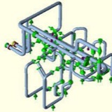
API 650 CALCULATIONS DATA FOR ANALYSIS:
* Input data
* Tank Diameter
* Nozzle Height above bottom Plate
* Nozzle Outer Diameter
* Shell Course Thickness
* Max Fluid Height above bottom plate
* delta Temperature
* Modulus of Elasticity
* Expansion Coefficient
* Fluid Specific Gravity
* Reinforcement on Shell or Nozzle
* Input data
* Tank Diameter
* Nozzle Height above bottom Plate
* Nozzle Outer Diameter
* Shell Course Thickness
* Max Fluid Height above bottom plate
* delta Temperature
* Modulus of Elasticity
* Expansion Coefficient
* Fluid Specific Gravity
* Reinforcement on Shell or Nozzle
Displacement for Settlement of Tank (vector1)
Displacement for Bulging & expansion tank (vector 2)
Displacement for Bulging & expansion tank (vector 2)
WHERE:
D1= DISPLACEMENT DUE TO SETTLEMENT
D2= DISPLACEMENT DUE TO BULGING EFFECT
D1= DISPLACEMENT DUE TO SETTLEMENT
D2= DISPLACEMENT DUE TO BULGING EFFECT
NOZZLE CHECK AS PER API 650:
* For external piping connected to tanks can be used for Tanks size greater than 36m (120 ft) in diameter.
* The purchaser can decide for the Tank size 36” and smaller as per API 650 design
* The recommendations of this appendix represent accepted practice for the design of shell openings in the lower half of the bottom shell course that have a minimum elevation from the tank bottom and meet the requirements of Table 5-6.
* For external piping connected to tanks can be used for Tanks size greater than 36m (120 ft) in diameter.
* The purchaser can decide for the Tank size 36” and smaller as per API 650 design
* The recommendations of this appendix represent accepted practice for the design of shell openings in the lower half of the bottom shell course that have a minimum elevation from the tank bottom and meet the requirements of Table 5-6.
1- Radial Growth of Shell
The unrestrained outward radial growth of the shell at the centre of the opening connection resulting from product head and/or thermal expansion shall be determined as follows:
The unrestrained outward radial growth of the shell at the centre of the opening connection resulting from product head and/or thermal expansion shall be determined as follows:
2- Rotation of Shell
The unrestrained rotation of the shell at the centre of the nozzle-shell connection resulting from product head shall be determined as follows:
The unrestrained rotation of the shell at the centre of the nozzle-shell connection resulting from product head shall be determined as follows:
The allowable Nozzle load can be calculated as per Appendix P- (p.2.7) or the allowable loads can be used which will be furnished by Vendor/ Mechanical Static.