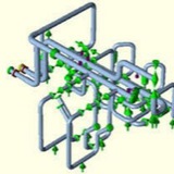
Application:
Vibrations can be generated inside a system by mechanical or hydrodynamic processes, or may result from external sources such as wind loads, traffic vibrations, or earthquakes. Excessive vibrations can cause serious damage to pipe systems. Protecting them requires special components that do not restrain thermal displacements of the piping system. Viscoelastic dampers have proved in practice to offer reliable protection for pipe systems and installations. In particular, vibrations caused by sudden peak loads can be reduced to an acceptable level by such dampers.
Vibrations can be generated inside a system by mechanical or hydrodynamic processes, or may result from external sources such as wind loads, traffic vibrations, or earthquakes. Excessive vibrations can cause serious damage to pipe systems. Protecting them requires special components that do not restrain thermal displacements of the piping system. Viscoelastic dampers have proved in practice to offer reliable protection for pipe systems and installations. In particular, vibrations caused by sudden peak loads can be reduced to an acceptable level by such dampers.
Scope of performance:
Load: 2.5 kN to 100kN
Frequency range: up to 35 Hz
Temperature range: +20 to +80°C and -10 to +40°C
Travel range: up to 50 mm
Load: 2.5 kN to 100kN
Frequency range: up to 35 Hz
Temperature range: +20 to +80°C and -10 to +40°C
Travel range: up to 50 mm
An example of a pump casing analysis involved a horizontal pump in a critical slurry service. In this example, the analysis focused on evaluating the stress and deflection of a casing when operating under full pressure with various specified nozzle loads. The model included the suction/ discharge volutes, nuts and bolts, and back plate (Figure 1). To determine the structural integrity of the casing design under internal pressure and nozzle loads, a detailed finite element analysis was conducted with the model including the slurry pump casing, the respective hub disc cover (back plate), nuts and bolts, and suction/ discharge volute provided by the customer. The solid model assembly of all the parts was analyzed using Solidworks and ANSYS.
Nonlinear contact analyses were performed with the hub disc cover and the suction/ discharge scrolls bolted to the casing. The peak von-Mises stress of the assembly, and the peak stress locations, were determined and compared to stress criteria per ASME B&PV Code Section VIII, Division 2. Using stress linearization techniques across the pump casing at this peak stress location, the membrane and membrane-plus-bending stresses were below their respective allowable limits. The local peak stresses were determined to be acceptable.
Settlement of a pipe support foundation is usually not a big deal to assess. A local piping flexibility model will reveal if the settled support keeps the pipe bending stresses within the allowable codes and, if the bending stresses are unacceptable, modifying the support and monitor periodically for further settlement is normally a quite manageable task. However, if settlement is occurring site-wide at a large site due to errors in the pre-construction soil surveys, the problem quickly becomes unmanageable.
Differential settlement can have an impact on a piping circuit in a number of modes:
1-Excessive bending stress may cause cracking of pipe and fittings.
2-Flanges may leak.
3-Elbows or TEEs may collapse.
4-Rotating Equipment Nozzles – rotating machinery is sensitive to even small amounts of deformation and are excluded from this scope.
5-Vessel nozzles – experience shows that a significant amount of deformation of a vessel nozzle due to bending can be tolerated without causing cracking or collapse of the vessel wall.
2-Flanges may leak.
3-Elbows or TEEs may collapse.
4-Rotating Equipment Nozzles – rotating machinery is sensitive to even small amounts of deformation and are excluded from this scope.
5-Vessel nozzles – experience shows that a significant amount of deformation of a vessel nozzle due to bending can be tolerated without causing cracking or collapse of the vessel wall.