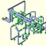
How to Avoid Conflict Between Pipe Stress and Vibration Analysis:
When machinery is involved in the piping system, the same consultants performing the dynamic mechanical Finite Element Analysis (FEA) should also complete the Pipe Stress Analysis. This will avoid conflicts between stiffness assumptions and requirements for supports, and also expedite a solution. Typically dynamic mechanical analysis will specify high stiffness supports, while piping flexibility analysis will require flexible supports. It is important to simultaneously consider both static and dynamic requirements.
Controlling vibration, and vibratory stress typically involves restraining the pipe. It also requires closer spacing of pipe supports (between clamps) to raise the mechanical natural frequency of the pipe to avoid resonance. Vibration control standards also require that pipe supports have enough stiffness to stop vibration at the support and caution against the use of hangers and guides.
Pipe Stress Analysis mitigates static deflections and stresses and typically involves selectively providing flexibility with a mixture of rest supports, guides, line stops, hangers, spring supports, and hold downs.
Recommendations for the pipe stress analysis can be directly opposite to the vibration design requirements. This conflict can, and does, result in significant confusion and problems during construction and operations.
To avoid this conflict, the standard industry approach is to have the same consultant perform both the vibration analysis and the piping stress analysis. This ensures the vibration control and piping design are adequately addressed, including realistic pipe support stiffness assumptions, and use of vibratory clamps/restraints that have enough flexibility for thermal growth.
This media is not supported in your browser
VIEW IN TELEGRAM
axial Expansion Joint
This media is not supported in your browser
VIEW IN TELEGRAM
Lateral Expansion Joint
This media is not supported in your browser
VIEW IN TELEGRAM
Angular (Hinged) Expansion Joint
Topic:
Is it necessary to install an expansion joint at pump discharge piping?
Is it necessary to install an expansion joint at pump discharge piping?
Expansion joints can be of great benefit in a pumping system when used properly. They are, however, only needed when pipe strain is present. In addition, the correct installation of an expansion joint is also necessary.
It is not simply a matter of bolting them into the pipeline. This merely transfers the strain through the joint and onto the pump casing, which will ultimately cause seal and bearing failure. In order to protect the pump from such problems, it is necessary to independently secure the end of the expansion joint closest to the pump. This allows the expansion joint to absorb the entire strain coming from the pipeline and thus protects the pump.
It is not simply a matter of bolting them into the pipeline. This merely transfers the strain through the joint and onto the pump casing, which will ultimately cause seal and bearing failure. In order to protect the pump from such problems, it is necessary to independently secure the end of the expansion joint closest to the pump. This allows the expansion joint to absorb the entire strain coming from the pipeline and thus protects the pump.
2 - The use of expansion (or flexible) pipe joints in a pump system that has no excessive temperature differential problems is only necessary when the pipe fitters installing the piping are unable or unwilling to install the piping without imposing any strain on the pump nozzles.
When they are used, it should be identified why theyre being used. The most common reason is to protect the pump against pipe strain that may be imposed by the movement of the piping during system operation. In such case, the side of the flexible pipe joint closest to the pump needs to be independently supported and secured against movement. This allows all the movement of the piping to be absorbed by the flexible joint, and none of it transferred to the pump.
Another thing to note is that an expansion joint will not necessary accommodate radial movement of the piping. Some of them are designed to accommodate only axial movement where the pipe and pump flanges are trying to get closer together or further apart. These are of no value against poor piping misalignment or thermal movement of the piping.
When they are used, it should be identified why theyre being used. The most common reason is to protect the pump against pipe strain that may be imposed by the movement of the piping during system operation. In such case, the side of the flexible pipe joint closest to the pump needs to be independently supported and secured against movement. This allows all the movement of the piping to be absorbed by the flexible joint, and none of it transferred to the pump.
Another thing to note is that an expansion joint will not necessary accommodate radial movement of the piping. Some of them are designed to accommodate only axial movement where the pipe and pump flanges are trying to get closer together or further apart. These are of no value against poor piping misalignment or thermal movement of the piping.
What is PTB-3
ASME problem sample manuals PTB-3 and PTB-4 are well kept secrets. The samples that used to be in the back of ASME VIII-1 in Appendix L have been changed, expanded and published as PTB-4. The ASME VIII-2 rewritten in 2007 got its own new PTB-3 problem sample manual in 2010. PTB-3 contains worked examples with numerical results. Although meant more as an educational guide than a verification set, here we compare our own results in both ABAQUS and SolidWorks against published PTB-3 results.
ASME problem sample manuals PTB-3 and PTB-4 are well kept secrets. The samples that used to be in the back of ASME VIII-1 in Appendix L have been changed, expanded and published as PTB-4. The ASME VIII-2 rewritten in 2007 got its own new PTB-3 problem sample manual in 2010. PTB-3 contains worked examples with numerical results. Although meant more as an educational guide than a verification set, here we compare our own results in both ABAQUS and SolidWorks against published PTB-3 results.
PTB-3 Example E5.2.1 and E5.3.2
PTB-3 example E5.2.1 “Elastic Stress Analysis” covers the correct use of stress linearization and provides numerical results. The same model is used for sample E5.3.2 “Elastic Analysis”. Here both are run.
PTB-3 example E5.2.1 “Elastic Stress Analysis” covers the correct use of stress linearization and provides numerical results. The same model is used for sample E5.3.2 “Elastic Analysis”. Here both are run.
[From E5.2.1] Evaluate the vessel top head and shell region for compliance with respect to the elastic stress analysis criteria for plastic collapse provided in [VIII-2] paragraph 5.2.2. Do not include the standard flanges or NPS 6 piping in the assessment for compliance to allowable stresses. Internal pressure is the only load that is to be considered. Relevant design data and geometry are provided below and in Figures E5.2.1-1 and E5.2.1-2.
In other words analyse the head and a nozzle in the top of a pressure vessel to determine its acceptability against ASME code rules for FEA. The instructions for E5.3.2 are: