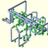
Documents required for Stress Analysis:
1- Tank G.A. drawing indicating nozzle elevation, nozzle projection.
2- Allowable load for tank nozzle as per vendor/manufacturer, if available.
3- Piping isometric, Line list, P&ID etc.
4- Soil settlement data of that region as per civil department.
1- Tank G.A. drawing indicating nozzle elevation, nozzle projection.
2- Allowable load for tank nozzle as per vendor/manufacturer, if available.
3- Piping isometric, Line list, P&ID etc.
4- Soil settlement data of that region as per civil department.
Modelling Procedure in Caesar II:
1- Model the nozzle flange (10-20) as per tank flange pressure rating.
2- Model the projection as pipe element (20-30) with same pipe diameter & schedule given in the drawing for the nozzle up to pipe and tank intersection.
3- For tanks having diameter less than 36 meter model 40-50 and 50-60 in the same way as followed for normal pressure vessels. Provide anchor at node 60 with CNODE at 61. Add the settlement displacement if any at node 61.
1- Model the nozzle flange (10-20) as per tank flange pressure rating.
2- Model the projection as pipe element (20-30) with same pipe diameter & schedule given in the drawing for the nozzle up to pipe and tank intersection.
3- For tanks having diameter less than 36 meter model 40-50 and 50-60 in the same way as followed for normal pressure vessels. Provide anchor at node 60 with CNODE at 61. Add the settlement displacement if any at node 61.
1- Following steps to be taken when doing the stress analysis for the lines connected to tank having diameter more than 36 meter:
2- Engineering/Process data sheet to be obtained from Process team to evaluate parameter (Radial Growth, unrestrained rotation, allowable forces and moments) as per API 650 as shown in the following figure:
2- Engineering/Process data sheet to be obtained from Process team to evaluate parameter (Radial Growth, unrestrained rotation, allowable forces and moments) as per API 650 as shown in the following figure:
Note: Here, Tank Coefficient of thermal expansion and modulus of elasticity can be obtained from API 650 (2007 Edition) Appendix P, ANSI B 31.3, or alternatively from any engineering handbooks.
3- Temperature change shall be based on the temperature at which nozzle to be checked. If required both can be entered in successive single run to obtain nozzle movement.)
4- “Start run” option to be executed to get the API 650 flexibility calculation and parameter as shown in the following figure
3- Temperature change shall be based on the temperature at which nozzle to be checked. If required both can be entered in successive single run to obtain nozzle movement.)
4- “Start run” option to be executed to get the API 650 flexibility calculation and parameter as shown in the following figure
5- Radial Growth, unrestrained longitudinal rotation (as calculated from API 650 spreadsheet) to be inserted in the displacement vector as shown below with correct orientation and direction. (See the sample attached here with).
6- In addition to normal load cases, following cases, in general, shall be included for tank piping analysis,
L1 W+P1+T1+D1+D3………….OPE
L2 W+P1+T2+D2+D3………….OPE
L3 W+P1………………….SUS
L4 L1-L3………………….EXP
L5 L2-L3………………….EXP
Where, D1 & D2 represent displacement vector as per API 650 for operating and design condition respectively and D3 represents tank settlement, if any.
L1 W+P1+T1+D1+D3………….OPE
L2 W+P1+T2+D2+D3………….OPE
L3 W+P1………………….SUS
L4 L1-L3………………….EXP
L5 L2-L3………………….EXP
Where, D1 & D2 represent displacement vector as per API 650 for operating and design condition respectively and D3 represents tank settlement, if any.
Nozzle Loading Checking:
1- To be checked as per “APPENDIX P” OF API 650 (as shown in Caesar API 650 spreadsheet) for Tanks having diameter larger than 36 M(120 ft).
2- For Tanks smaller than 36 m (120 ft) in diameter :
2-1- Vendor has to provide allowable load for the connected nozzles.
2-2- To be checked with Nozzle-Pro / WRC 107/ FEA/ WRC 297/ for Tanks.
1- To be checked as per “APPENDIX P” OF API 650 (as shown in Caesar API 650 spreadsheet) for Tanks having diameter larger than 36 M(120 ft).
2- For Tanks smaller than 36 m (120 ft) in diameter :
2-1- Vendor has to provide allowable load for the connected nozzles.
2-2- To be checked with Nozzle-Pro / WRC 107/ FEA/ WRC 297/ for Tanks.
Obviously, in the case of isolation of any component, because of the relative displacement between the ground and insulated tank that is generated during the earthquake, must be equipped with appropriate expansion joints, the inlet and outlet pipes. Section of pipe in real scale with 2 universal joints and angled able to absorb relative displacements of 80 cm. (Experimental Test, System Nidyon seismic shaking table).
ASME B31.3 2014 Edition, including:
Addressed the code standard requirement to consider sustained (and occasional) stress in all support conditions. New static load cases, called alternate sustained or alternate occasional cases, depend upon the support configuration of a converged operating condition. This condition addresses systems where non-linear supports are active in some operating conditions and inactive in others. The alternate support condition is indicated using the new Alternate SUS/OCC check box in the Static Analysis – Load Case Editor.
Added two new load case templates (.tpl files) for use when recommending load cases, which include support for the alternate SUS/OCC load cases. The template files include: TPL – the updated default load case template, which recommends alternate sustained load casee for jobs including the B31.3 code and LOAD_EXP.TPL – includes all expansion load cases between different operating conditions. (This was the default template in CAESAR II 2014.)
Updated materials to support the latest code edition. Updated B31.3 materials, including changes to expansion coefficients (Ec), weld reduction factors (W), and elastic modulus (EM) values. Updated allowable stress values for material 341 (A789 S32750) and 342 (A790 S32750). Corrected low temperature allowable values to match the code standard.
Moved the B31.3 Implement Appendix P configuration setting to SIFs and Stresses >Legacy Settings as the B31.3 code standard no longer refers to Appendix P.
Added appropriate warnings and notes to the error checking module and the output reports to account for the code updates.
ASME B31.1, 2014 Edition.
ASME B31.9, 2014 Edition.
ASME B31.8, 2014 Edition, including a small revision to the biaxial state of stress formula (Sc), according to code Paragraph 833.4. You can find this formula in the CAESAR II Quick Reference Guide.
Addressed the code standard requirement to consider sustained (and occasional) stress in all support conditions. New static load cases, called alternate sustained or alternate occasional cases, depend upon the support configuration of a converged operating condition. This condition addresses systems where non-linear supports are active in some operating conditions and inactive in others. The alternate support condition is indicated using the new Alternate SUS/OCC check box in the Static Analysis – Load Case Editor.
Added two new load case templates (.tpl files) for use when recommending load cases, which include support for the alternate SUS/OCC load cases. The template files include: TPL – the updated default load case template, which recommends alternate sustained load casee for jobs including the B31.3 code and LOAD_EXP.TPL – includes all expansion load cases between different operating conditions. (This was the default template in CAESAR II 2014.)
Updated materials to support the latest code edition. Updated B31.3 materials, including changes to expansion coefficients (Ec), weld reduction factors (W), and elastic modulus (EM) values. Updated allowable stress values for material 341 (A789 S32750) and 342 (A790 S32750). Corrected low temperature allowable values to match the code standard.
Moved the B31.3 Implement Appendix P configuration setting to SIFs and Stresses >Legacy Settings as the B31.3 code standard no longer refers to Appendix P.
Added appropriate warnings and notes to the error checking module and the output reports to account for the code updates.
ASME B31.1, 2014 Edition.
ASME B31.9, 2014 Edition.
ASME B31.8, 2014 Edition, including a small revision to the biaxial state of stress formula (Sc), according to code Paragraph 833.4. You can find this formula in the CAESAR II Quick Reference Guide.
— National Building Code of Canada (NBC) Seismic and Wind Codes, 2010 Edition.
— ASCE 7 2010 Edition and IBC 2012 Edition wind code standards, including a change in the wind load reduction factor.
— ASCE 7 2010 Edition and IBC 2012 Edition wind code standards, including a change in the wind load reduction factor.
Equipment Codes:
API 661, 7th Edition.
API 560, 4th Edition.
API 610, 11th Edition.
API 617, 8th Edition.
API 661, 7th Edition.
API 560, 4th Edition.
API 610, 11th Edition.
API 617, 8th Edition.