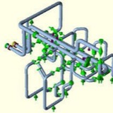
One of the problems with the subject piping system that caused
the elastic follow-up condition is that it was “close coupled”.
Close coupling occurs when a system is inflexible by virtue of
its routing and restraint scheme. The two closely spaced 24” O.
D. turbine leads rise only twelve feet and lack sufficient
flexibility to adequately absorb the expansion developed from
the other one hundred five feet of station piping (Fig. No. 4).
In addition, the situation is further aggravated by the limit stop
installed at the turbine centerline (Fig. No. 5). By virtue of its
design and location, it tended to restrict the piping’s axial
displacement and rotation as well as isolate the north lead,
thereby causing considerable bending, especially in the vicinity
of the failure.
the elastic follow-up condition is that it was “close coupled”.
Close coupling occurs when a system is inflexible by virtue of
its routing and restraint scheme. The two closely spaced 24” O.
D. turbine leads rise only twelve feet and lack sufficient
flexibility to adequately absorb the expansion developed from
the other one hundred five feet of station piping (Fig. No. 4).
In addition, the situation is further aggravated by the limit stop
installed at the turbine centerline (Fig. No. 5). By virtue of its
design and location, it tended to restrict the piping’s axial
displacement and rotation as well as isolate the north lead,
thereby causing considerable bending, especially in the vicinity
of the failure.
One method of verifying if the piping was close coupled is to
test its sensitivity to small changes in the boundary conditions.
The boundary conditions selected were the thermal
displacements of the turbine connections and the free
movement gap of the restraint. Close coupling occurs if the
calculated restraint loads and piping stresses vary greatly with
only minor boundary changes that are well within installation
and operating tolerances.
Using the "as-exists” elastic stress analysis as the basis,
variations were first made to the free movement gap of the
restraint. When the gap was changed by only 1/32", the
combined bending and axial stress at the failure varied by
nearly 1,000 psi from the base values.
Then, the turbine reheat connections’ displacements were
varied. When the thermal displacements of the connections
were changed by only ¼”, the load on the restraint increased
and the stresses at the failure increased significantly.
This high sensitivity of the piping to small changes suggests a
strong susceptibility to inelastic strain resulting in elastic
follow-up. This is especially true since the boundary condition
variations are not unreasonable. That is, restraint tolerancesand equipment displacement tolerances of fractions of an inch
are difficult to maintain. With systems such as this, the
boundary conditions cannot be modeled precisely enough to provide assurance that the elastic analysis accurately calculates
the stresses.
test its sensitivity to small changes in the boundary conditions.
The boundary conditions selected were the thermal
displacements of the turbine connections and the free
movement gap of the restraint. Close coupling occurs if the
calculated restraint loads and piping stresses vary greatly with
only minor boundary changes that are well within installation
and operating tolerances.
Using the "as-exists” elastic stress analysis as the basis,
variations were first made to the free movement gap of the
restraint. When the gap was changed by only 1/32", the
combined bending and axial stress at the failure varied by
nearly 1,000 psi from the base values.
Then, the turbine reheat connections’ displacements were
varied. When the thermal displacements of the connections
were changed by only ¼”, the load on the restraint increased
and the stresses at the failure increased significantly.
This high sensitivity of the piping to small changes suggests a
strong susceptibility to inelastic strain resulting in elastic
follow-up. This is especially true since the boundary condition
variations are not unreasonable. That is, restraint tolerancesand equipment displacement tolerances of fractions of an inch
are difficult to maintain. With systems such as this, the
boundary conditions cannot be modeled precisely enough to provide assurance that the elastic analysis accurately calculates
the stresses.
In contrast, a similar variation of the boiler connection
movements had little effect on the local stresses and restraint
loads. This indicated that the remainder of the hot reheat
piping was not close coupled and hence only the piping near
the turbine was prone to elastic follow-up.
The combination of the inflexible close coupling of the turbinepiping
risers, the influence of the axial restraint and the lateral's
geometry prevented the system from self-stress relieving
locally. The piping became highly sensitive to small changes in
displacements. This favors the potential for accelerated creep
damage. The more highly stressed piping near the turbine is
then subject to excessive plastic deformation and strain
concentrations due to elastic follow-up from the lower stressed
stiffer portions of the piping (i. e. the header).
To recognize the possibility of elastic follow-up conditions
requires an understanding of the phenomenon and experience
in analysis, design and evaluations. As detailed above, the
standard elastic stress analysis did not indicate a problem.
However, an experienced piping engineer should recognize
when the piping is close coupled around the turbine.
Sensitivity analyses involving variations of the turbine
movements, cold spring and limit stopgaps would provide
sufficient data to show that the pipe could be susceptible to
elastic follow-up. Therefore the secondary stresses convert to
the primary level. Hence, it is probable that the actual primary
stresses, especially the bending stresses, at the least stiff
regions of the subject area, far exceed those calculated by the
elastic analysis. As a result the pipe should be rerouted.
movements had little effect on the local stresses and restraint
loads. This indicated that the remainder of the hot reheat
piping was not close coupled and hence only the piping near
the turbine was prone to elastic follow-up.
The combination of the inflexible close coupling of the turbinepiping
risers, the influence of the axial restraint and the lateral's
geometry prevented the system from self-stress relieving
locally. The piping became highly sensitive to small changes in
displacements. This favors the potential for accelerated creep
damage. The more highly stressed piping near the turbine is
then subject to excessive plastic deformation and strain
concentrations due to elastic follow-up from the lower stressed
stiffer portions of the piping (i. e. the header).
To recognize the possibility of elastic follow-up conditions
requires an understanding of the phenomenon and experience
in analysis, design and evaluations. As detailed above, the
standard elastic stress analysis did not indicate a problem.
However, an experienced piping engineer should recognize
when the piping is close coupled around the turbine.
Sensitivity analyses involving variations of the turbine
movements, cold spring and limit stopgaps would provide
sufficient data to show that the pipe could be susceptible to
elastic follow-up. Therefore the secondary stresses convert to
the primary level. Hence, it is probable that the actual primary
stresses, especially the bending stresses, at the least stiff
regions of the subject area, far exceed those calculated by the
elastic analysis. As a result the pipe should be rerouted.
Step by Step Methods for WRC 107 and WRC 297 Checking in Caesar II
Whenever Pressure Vessel or Heat exchanger (Static Equipments) nozzle loads exceeds the allowable values provided by Vendors (Equipment manufacturer) or standard project specific tables (guidelines), the piping stress professional is permitted to use WRC 107/297 (or any other FEA) to check the stresses at the Nozzle-Shell junction point and check the stresses with allowable values provided by Codes. If the stresses are found to be within allowable limit then the load and moment values can be accepted without any hesitation. However there are some boundary conditions which must be met before using WRC. This small write up will try to explain the required details for performing WRC 107 and WRC 297 using Caesar II and step by step method for performing WRC check. Both WRC 107 and WRC 297 deal with “local” stress states in the vicinity of an attachment to a vessel or pipe. As indicated by their titles, WRC-107 can be used for attachments to both spherical and cylindrical shells while WRC-297 only addresses cylinder to cylinder connections. While both bulletins are used for nozzle connection. WRC-107 is based on un-penetrated shell, while WRC-297 assumes a circular opening in vessel. Furthermore, WRC-107 defines values for solid and hollow attachments of either round and rectangular shape for spherical shells but drops the solid/hollow distinction for attachments to cylindrical shells. WRC-297, on the other hand, is intended only for cylindrical nozzles attached to cylindrical shells.
Boundary condition for using WRC 107:
To determine whether WRC 107 bulletin can be used for local stress checking the following geometry guidelines must be met:
1. d/D<0.33
2. Dm/T= (D-T)/T>50 (Here, T=Vessel Thickness, Dm=mean diameter of vessel)
To determine whether WRC 107 bulletin can be used for local stress checking the following geometry guidelines must be met:
1. d/D<0.33
2. Dm/T= (D-T)/T>50 (Here, T=Vessel Thickness, Dm=mean diameter of vessel)
Boundary condition for using WRC 297:
To determine whether WRC 107 bulletin can be used for local stress checking the following geometry guidelines must be met:
1. d/D<=0.5
2. d/t>=20 and d/t<=100 (Here t=nozzle thickness)
3. D/T>=20 and D/T<=2500
4. d/T>=5
5. Nozzle must be isolated (it may not be close to a discontinuity) – not within 2√(DT) on vessel and not within 2√(dt) on nozzle
To determine whether WRC 107 bulletin can be used for local stress checking the following geometry guidelines must be met:
1. d/D<=0.5
2. d/t>=20 and d/t<=100 (Here t=nozzle thickness)
3. D/T>=20 and D/T<=2500
4. d/T>=5
5. Nozzle must be isolated (it may not be close to a discontinuity) – not within 2√(DT) on vessel and not within 2√(dt) on nozzle