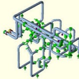
A piping support hardware is an assembly of mechanical parts such as beams, columns, brace, connectors, pins, bolts, nuts and are designed taking into account the conditions described in the previous paragraph and is connected to the building structure.
The external area of the piping and the support structure hardware at the restrained point touch each other and, because of this, any aspects of the direct contact between surfaces and design parameters of piping and supports structure has to be analyzed. This way, in a structural viewpoint, we outline the most relevant parameters, such as stiffness, friction forces, gap and localized pipe stress of the design applied to the contact surface between piping and supports.
Normally, a stress analysis of a pipeline is performed and the resulting loads on pipe restrictions are forwarded to a team which develops a support design. This independent behavior between a piping design and support design is grounded in the assumption that the support has a quasi rigid behavior.
piping support hardware stiffness in the direction of load:
maximum deflection of 1.6 mm in the direction of load, for combining loads in the
abnormal operation service.
abnormal operation service.
High temperature, high pressure steam piping can fail for many
reasons. This can include some combination of metallurgical,
operational, fabrication, erection and design short comings.
This has proven that high-energy piping systems are not
maintenance free and have a finite service life.\
reasons. This can include some combination of metallurgical,
operational, fabrication, erection and design short comings.
This has proven that high-energy piping systems are not
maintenance free and have a finite service life.\
The ASME B31.1 Code states that piping is “subjected to strain
concentrations due to elastic follow-up of the stiffer or lower
stressed portions."
concentrations due to elastic follow-up of the stiffer or lower
stressed portions."
Advanced creep stress analysis is one
method to do this. However, it is still important to recognize
the conditions that can reduce pipe life and addressing them
method to do this. However, it is still important to recognize
the conditions that can reduce pipe life and addressing them
The Code describes several piping system geometries that can
be the catalyst for elastic follow-up. They Include:
1. Smaller pipe that operates in a higher stress range than
the larger or stiffer pipe to which it is connected.
2. The introduction of reducers or other configurations in
which the pipe section modulus becomes smaller.
3. Pipe material that is, or becomes, locally weaker.
4. The use of insufficient offset to absorb the expansion
strain of the major portion of the piping system.
be the catalyst for elastic follow-up. They Include:
1. Smaller pipe that operates in a higher stress range than
the larger or stiffer pipe to which it is connected.
2. The introduction of reducers or other configurations in
which the pipe section modulus becomes smaller.
3. Pipe material that is, or becomes, locally weaker.
4. The use of insufficient offset to absorb the expansion
strain of the major portion of the piping system.
The Code acknowledges that piping systems self-stress relieve.
This phenomenon occurs when the thermal expansion stresses
in a piping system tend to "relax in the hot condition." The
expansion stresses then appear in the cold condition. Because
they are not consistently applied, these stresses are treated as
secondary stresses. Expansion stresses are compared to an
allowable stress range, which is equivalent to the weighted sum
of the Code's cold (Sc) and hot (Sh) stress allowables.
This phenomenon occurs when the thermal expansion stresses
in a piping system tend to "relax in the hot condition." The
expansion stresses then appear in the cold condition. Because
they are not consistently applied, these stresses are treated as
secondary stresses. Expansion stresses are compared to an
allowable stress range, which is equivalent to the weighted sum
of the Code's cold (Sc) and hot (Sh) stress allowables.
However, the pipe routing and restraint configurations listed
above may not allow high temperature piping to self-stress
relieve. This is a form of elastic follow-up.
above may not allow high temperature piping to self-stress
relieve. This is a form of elastic follow-up.
One of the problems with the subject piping system that caused
the elastic follow-up condition is that it was “close coupled”.
Close coupling occurs when a system is inflexible by virtue of
its routing and restraint scheme. The two closely spaced 24” O.
D. turbine leads rise only twelve feet and lack sufficient
flexibility to adequately absorb the expansion developed from
the other one hundred five feet of station piping (Fig. No. 4).
In addition, the situation is further aggravated by the limit stop
installed at the turbine centerline (Fig. No. 5). By virtue of its
design and location, it tended to restrict the piping’s axial
displacement and rotation as well as isolate the north lead,
thereby causing considerable bending, especially in the vicinity
of the failure.
the elastic follow-up condition is that it was “close coupled”.
Close coupling occurs when a system is inflexible by virtue of
its routing and restraint scheme. The two closely spaced 24” O.
D. turbine leads rise only twelve feet and lack sufficient
flexibility to adequately absorb the expansion developed from
the other one hundred five feet of station piping (Fig. No. 4).
In addition, the situation is further aggravated by the limit stop
installed at the turbine centerline (Fig. No. 5). By virtue of its
design and location, it tended to restrict the piping’s axial
displacement and rotation as well as isolate the north lead,
thereby causing considerable bending, especially in the vicinity
of the failure.
One method of verifying if the piping was close coupled is to
test its sensitivity to small changes in the boundary conditions.
The boundary conditions selected were the thermal
displacements of the turbine connections and the free
movement gap of the restraint. Close coupling occurs if the
calculated restraint loads and piping stresses vary greatly with
only minor boundary changes that are well within installation
and operating tolerances.
Using the "as-exists” elastic stress analysis as the basis,
variations were first made to the free movement gap of the
restraint. When the gap was changed by only 1/32", the
combined bending and axial stress at the failure varied by
nearly 1,000 psi from the base values.
Then, the turbine reheat connections’ displacements were
varied. When the thermal displacements of the connections
were changed by only ¼”, the load on the restraint increased
and the stresses at the failure increased significantly.
This high sensitivity of the piping to small changes suggests a
strong susceptibility to inelastic strain resulting in elastic
follow-up. This is especially true since the boundary condition
variations are not unreasonable. That is, restraint tolerancesand equipment displacement tolerances of fractions of an inch
are difficult to maintain. With systems such as this, the
boundary conditions cannot be modeled precisely enough to provide assurance that the elastic analysis accurately calculates
the stresses.
test its sensitivity to small changes in the boundary conditions.
The boundary conditions selected were the thermal
displacements of the turbine connections and the free
movement gap of the restraint. Close coupling occurs if the
calculated restraint loads and piping stresses vary greatly with
only minor boundary changes that are well within installation
and operating tolerances.
Using the "as-exists” elastic stress analysis as the basis,
variations were first made to the free movement gap of the
restraint. When the gap was changed by only 1/32", the
combined bending and axial stress at the failure varied by
nearly 1,000 psi from the base values.
Then, the turbine reheat connections’ displacements were
varied. When the thermal displacements of the connections
were changed by only ¼”, the load on the restraint increased
and the stresses at the failure increased significantly.
This high sensitivity of the piping to small changes suggests a
strong susceptibility to inelastic strain resulting in elastic
follow-up. This is especially true since the boundary condition
variations are not unreasonable. That is, restraint tolerancesand equipment displacement tolerances of fractions of an inch
are difficult to maintain. With systems such as this, the
boundary conditions cannot be modeled precisely enough to provide assurance that the elastic analysis accurately calculates
the stresses.