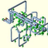
The structural integrity of a piping system is ensured by providing minimum piping wall thickness (controlling the hoop stress) and an adequate design of supports for holding the pipe in place (controlling the longitudinal stress). In a mathematical model to perform the stress analysis of a piping system every point is associated with six degrees of freedom (DOF): three translations and three rotations. Without restriction, the pipe can move and rotate in the x, y and z directions, but if the movement is not allowed, loads will arise in the restricted directions.
Piping Support is a generic designation used to describe an assembly of structural elements, which restrict one or more degrees of freedom of the piping system, resulting in loads that are transmitted to the building structure. By this approach, the type and function of the piping support are established and summarized in the Table 7.
A non-rigid piping support is a non linear type of support that restrains the movement in the downward direction and is applied to sustain the piping weight and the loads acting in the same direction. A dynamic support is a type of support that restrains only dynamic loads due to earthquakes, water hammer, relief valve discharge, etc.
Piping support can be built with several structural configurations, usually named “Piping Support Hardware”, which depends on the:
function of the support;
distance between the pipe and building structure;
available space in order to arrange the structural elements of the piping support.
function of the support;
distance between the pipe and building structure;
available space in order to arrange the structural elements of the piping support.
A piping support hardware is an assembly of mechanical parts such as beams, columns, brace, connectors, pins, bolts, nuts and are designed taking into account the conditions described in the previous paragraph and is connected to the building structure.
The external area of the piping and the support structure hardware at the restrained point touch each other and, because of this, any aspects of the direct contact between surfaces and design parameters of piping and supports structure has to be analyzed. This way, in a structural viewpoint, we outline the most relevant parameters, such as stiffness, friction forces, gap and localized pipe stress of the design applied to the contact surface between piping and supports.
Normally, a stress analysis of a pipeline is performed and the resulting loads on pipe restrictions are forwarded to a team which develops a support design. This independent behavior between a piping design and support design is grounded in the assumption that the support has a quasi rigid behavior.
piping support hardware stiffness in the direction of load:
maximum deflection of 1.6 mm in the direction of load, for combining loads in the
abnormal operation service.
abnormal operation service.
High temperature, high pressure steam piping can fail for many
reasons. This can include some combination of metallurgical,
operational, fabrication, erection and design short comings.
This has proven that high-energy piping systems are not
maintenance free and have a finite service life.\
reasons. This can include some combination of metallurgical,
operational, fabrication, erection and design short comings.
This has proven that high-energy piping systems are not
maintenance free and have a finite service life.\
The ASME B31.1 Code states that piping is “subjected to strain
concentrations due to elastic follow-up of the stiffer or lower
stressed portions."
concentrations due to elastic follow-up of the stiffer or lower
stressed portions."
Advanced creep stress analysis is one
method to do this. However, it is still important to recognize
the conditions that can reduce pipe life and addressing them
method to do this. However, it is still important to recognize
the conditions that can reduce pipe life and addressing them
The Code describes several piping system geometries that can
be the catalyst for elastic follow-up. They Include:
1. Smaller pipe that operates in a higher stress range than
the larger or stiffer pipe to which it is connected.
2. The introduction of reducers or other configurations in
which the pipe section modulus becomes smaller.
3. Pipe material that is, or becomes, locally weaker.
4. The use of insufficient offset to absorb the expansion
strain of the major portion of the piping system.
be the catalyst for elastic follow-up. They Include:
1. Smaller pipe that operates in a higher stress range than
the larger or stiffer pipe to which it is connected.
2. The introduction of reducers or other configurations in
which the pipe section modulus becomes smaller.
3. Pipe material that is, or becomes, locally weaker.
4. The use of insufficient offset to absorb the expansion
strain of the major portion of the piping system.