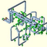
Let’s assume the shown system is subjected to slug flow. The parameters for the pipe are as mentioned below:
• Pipe: A106B, 6”, Sch 40
• CA=3 mm
• T1=100 degree C
• T2=75 degree C
• P1=15 bar
• Liquid Density=950 Kg/m^3
• Two phase Velocity=10.53 m/s
• CA=3 mm
• T1=100 degree C
• T2=75 degree C
• P1=15 bar
• Liquid Density=950 Kg/m^3
• Two phase Velocity=10.53 m/s
After modeling the piping system following conventional method we have to calculate the slug force and apply the same into the system. Normally all organizations have their excel spreadsheet to calculate Slug Force. A typical excel spreadsheet for slug force calculation is shown in the below attached figure for your reference.
So if we use a DLF of 2 then each of axial and orthogonal force will be 4240N. We have to incorporate this force in Caesar II input spreadsheet. Check the below mentioned figure for direction of forces.
Now we will input the axial and orthogonal forces at all changes in direction as shown in attached figure.
1- To enter forces click on the Forces button in Caesar II spreadsheet.
2- Provide the node number and magnitude of forces with proper direction.
3- Similarly input forces in all bends (other than vertically downward bends).
2- Provide the node number and magnitude of forces with proper direction.
3- Similarly input forces in all bends (other than vertically downward bends).
Next step is to prepare the required load cases. Few additional load cases need to be prepared for static analysis of slug force. The same has been shown in the below mentioned figure.
* Prepare the load cases as mentioned in the figure.
* Make stress types as occasional
* Use combination methods as Scalar
* Make stress types as occasional
* Use combination methods as Scalar
* Additionally We have to check code compliance for load cases L14 to L17 and ensure that the values are well within code allowable values.
* We have to check forces and displacements for load cases L1 to L9.
* Refer below mentioned figures for reference:
* We have to check forces and displacements for load cases L1 to L9.
* Refer below mentioned figures for reference:
Keep all stresses, forces and displacements within allowable limit. If exceeds then try iteration with support location change, support type change or routing change.
Client: Morvarid petrochemical company
Location: Assalouyeh, Pars Special Economic Zone
TFA’s Responsibility:
Mechanical design of Flare Stack and piping and civil and structure design of flare system and installation manual
Location: Assalouyeh, Pars Special Economic Zone
TFA’s Responsibility:
Mechanical design of Flare Stack and piping and civil and structure design of flare system and installation manual