⬇️ Results
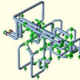
The analysis results showed that thrust blocks had been adequately sized concerning pressure thrust. Furthermore, it was observed that stress problems did not occur in piping that had been joined using coupling joints. For one critical section where coupling joints were used, the effect of settlement of thrust blocks was examined. It was concluded that piping with coupling joints is not sensitive to this problem due to the additional flexibility provided by the joints.
The analysis results showed that thrust blocks had been adequately sized concerning pressure thrust. Furthermore, it was observed that stress problems did not occur in piping that had been joined using coupling joints. For one critical section where coupling joints were used, the effect of settlement of thrust blocks was examined. It was concluded that piping with coupling joints is not sensitive to this problem due to the additional flexibility provided by the joints.
The most critical observations from the analysis were:
# The occurrence of high stresses at the elbows directly below the hydrants.
# The occurrence of high stresses in the case of settlements of thrust blocks.
# The occurrence of high stresses in the case of settlements of the concrete slabs supporting the hydrants.
# The occurrence of high stresses at the elbows directly below the hydrants.
# The occurrence of high stresses in the case of settlements of thrust blocks.
# The occurrence of high stresses in the case of settlements of the concrete slabs supporting the hydrants.
❗️It was shown in this assessment that the settlement of thrust blocks may be the main reason for high-stressed regions to occur. However, based on the knowledge that most settlement of thrust blocks would occur in the period immediately following installation, and the fact that no such failure had occurred after the last on-site intervention, a large-scale preventative intervention was not deemed necessary.
🔔Lessons Learned from Large-Diameter Pipe Failure Case Studies
⤵️. Failures of large diameter pipes can cause significant social, environmental and economic impacts. The actual failure mechanisms of buried pipes are difficult to isolate because many external and internal factors are commonly involved. Moreover, the major pipe breaks occur below the ground and the root cause of failure may be masked by the violent nature of the break. Detailed investigations were undertaken to examine and understand the failure mechanisms of buried large diameter cast iron water pipe breaks. We used various approaches to gathering field evidence from failed as well as unfailed pipes, numerical simulations, field instrumentation and full-scale laboratory pipe burst testing. Large diameter pipes tend to fail predominantly by longitudinal fracture. The failure mechanisms involving longitudinal fractures indicated that a large corrosion patch in the pipe barrel is commonly needed for pipe failure. This finding is in contrast to the belief that small pits are mostly responsible for failures. This means that many of the current condition assessment techniques currently targeting the detection of pits in pipes need to focus on the detection of larger patches of corrosion. The research also found that pipes fail by developing a crack first within a corrosion patch that could lead to water leakage until the crack grows sufficiently long to cause a major break. This concept is referred to as “leak before break” (LBB) for cast iron pipes. This concept can potentially be used for failure prevention of critical pipelines through improved leak detection.
⤵️. Failures of large diameter pipes can cause significant social, environmental and economic impacts. The actual failure mechanisms of buried pipes are difficult to isolate because many external and internal factors are commonly involved. Moreover, the major pipe breaks occur below the ground and the root cause of failure may be masked by the violent nature of the break. Detailed investigations were undertaken to examine and understand the failure mechanisms of buried large diameter cast iron water pipe breaks. We used various approaches to gathering field evidence from failed as well as unfailed pipes, numerical simulations, field instrumentation and full-scale laboratory pipe burst testing. Large diameter pipes tend to fail predominantly by longitudinal fracture. The failure mechanisms involving longitudinal fractures indicated that a large corrosion patch in the pipe barrel is commonly needed for pipe failure. This finding is in contrast to the belief that small pits are mostly responsible for failures. This means that many of the current condition assessment techniques currently targeting the detection of pits in pipes need to focus on the detection of larger patches of corrosion. The research also found that pipes fail by developing a crack first within a corrosion patch that could lead to water leakage until the crack grows sufficiently long to cause a major break. This concept is referred to as “leak before break” (LBB) for cast iron pipes. This concept can potentially be used for failure prevention of critical pipelines through improved leak detection.
🔔The Danger of Piping Failure Due to Acoustic-Induced Fatigue in Infrequent Operations
⤵️ Failure in piping due to acoustic-induced fatigue can be considered catastrophic as it could happen only after a few minutes of operation. Acoustic-induced fatigue occurs mainly in gas piping systems with high velocity where high energy is dissipated through pressure reducing stations and pipe branch connections. It usually results in pipe through wall longitudinal cracks, pipe detachment from saddle supports, and complete shear off of branch connections. There are existing design criteria to avoid acoustic-induced fatigue based on comparison of generated power level to an acceptable power level. This criterion is normally used for the design of pressure relief and flare piping where high gas velocity exceeding 50% of the speed of sound (i.e., 0.5 Mach) is expected. However, acoustic-induced fatigue has been experienced in systems due to intermittent operations. Two case studies are presented.
1- The first one is during a steam-out operation to clean a newly constructed steam header. During the cleaning operation, an orifice plate was used to control the flow in the steam header. Several pipe vents and drains failed due to fatigue in less than 1 h.
2- The second case is for drainage of compressed natural gas during process upset condition. Because of the high level buildup in the liquefied gas separator vessel, the drain valve was opened to release the pressurized liquefied gas to the relief system to reduce the level buildup. Wall cracks and several pipe support detachments were found in the system after the upset condition.
⤵️ Failure in piping due to acoustic-induced fatigue can be considered catastrophic as it could happen only after a few minutes of operation. Acoustic-induced fatigue occurs mainly in gas piping systems with high velocity where high energy is dissipated through pressure reducing stations and pipe branch connections. It usually results in pipe through wall longitudinal cracks, pipe detachment from saddle supports, and complete shear off of branch connections. There are existing design criteria to avoid acoustic-induced fatigue based on comparison of generated power level to an acceptable power level. This criterion is normally used for the design of pressure relief and flare piping where high gas velocity exceeding 50% of the speed of sound (i.e., 0.5 Mach) is expected. However, acoustic-induced fatigue has been experienced in systems due to intermittent operations. Two case studies are presented.
1- The first one is during a steam-out operation to clean a newly constructed steam header. During the cleaning operation, an orifice plate was used to control the flow in the steam header. Several pipe vents and drains failed due to fatigue in less than 1 h.
2- The second case is for drainage of compressed natural gas during process upset condition. Because of the high level buildup in the liquefied gas separator vessel, the drain valve was opened to release the pressurized liquefied gas to the relief system to reduce the level buildup. Wall cracks and several pipe support detachments were found in the system after the upset condition.
During the course of pipe stress analysis, we find a few lines in any complex project to have a very large diameter. Caesar II Support Modeling of such pipes always creates confusion on whether to consider radial thermal growth or to be modeled as centreline supporting. There is still confusion among several engineering organizations and the design approach varies. In this article, We will discuss pipe support modeling in Caesar-II, support selection, its detailing & functionality. In this article, Pipes /Pipelines having a diameter of more than 24’’ are considered large-diameter pipes.
What is Piping
| What is Piping
Piping Stress Analysis is the most important activity in Piping Design. Once, pipes are routed following design guidelines, those needs to be verified by piping stress analysis to ensure those will work smoothly throughout its design life. This article will…
Variable spring hanger supports are used at locations that are subjected to vertical thermal displacements. The size and type of variable spring hangers to be used depends on the load requirements and the method of installation. The actual load for which the spring is to support (hot condition), and the amount and direction of the pipe line movement from the cold to the hot position is required to properly determine sizes.