ساپورت گذاری سیستم پایپینگ.pdf
16.9 MB
Share ساپورت گذاری سیستم پایپینگ.pdf
Fabrication of pipe supports requires attention. How the pipe supports are prefabricated and how they are installed is important. Wrong prefabrication/installation of pipe supports could cause unwanted effects (high repair costs, failure of the pipe support etc.). Pipe supports often contain a mix of metallic materials together with non-metallic components. The fabrication of such items requires good workmanship. It starts with a good design and fabrication friendly solutions/philosophies, but also the fabrication process has its challenges. It is very important to follow up both vendors of pipe support standard details and the main fabricator contractor to ensure good workmanship in all phases of the pipe support fabrication.
Installation weld Guide/Stop – Welding guides adjacent to e.g a pipe support shoe is a challenge. Because the guide-weld towards the shoe needs to be from one side, the type of weld to be used is a challenge. A full pen. weld is not possible if we want the intended function between the guide and the shoe base plate. A type of K-weld could be evaluated.
PIPE SUPPORT FRAMEWORK
The prefabrication of the pipe support frames usually follows the standard and procedures for structural steel. However pipe supports may have a different material philosophy (using stainless steel like 316L or Lean Duplex). In those cases we may use hollow sections with thin wall (due to higher strength). such sections, attention should be made to the places where partly penetration welds are used (ref. highlighted weld in fig.). When we have a section wall thickness less than 6mm we might come in conflict with minimum weld size requirements. This needs to be clarified before design/fabrication starts.
The prefabrication of the pipe support frames usually follows the standard and procedures for structural steel. However pipe supports may have a different material philosophy (using stainless steel like 316L or Lean Duplex). In those cases we may use hollow sections with thin wall (due to higher strength). such sections, attention should be made to the places where partly penetration welds are used (ref. highlighted weld in fig.). When we have a section wall thickness less than 6mm we might come in conflict with minimum weld size requirements. This needs to be clarified before design/fabrication starts.
Pipe Support Small Bore Connection ⬇️
A challenging task regarding pipe support design is supporting of small bore connections (SBC) with a lump mass at the end (e.g. pipe vent/drain, instruments connection etc.). With this article, Pipe Support Verification’s aim is to give the basic thoughts of doing a good SBC support design.
We can divide the supporting of SBC in two categories:
Static effects – meaning the lump mass needs supporting because of large static loads.
Dynamic effects – meaning vibrations in the SBC caused by flow induced vibration (FIV), acoustic induced vibration (AIV) or equipment induced vibration (EIV).
The most challenging is the supporting due to dynamic effects. To find the SBC that require bracing, we need to evaluate where it is likely that vibrations can occur. Regarding FIV, the piping stress group usually do a FIV screening to find the LOF parameter (likelihood of failure) for the pipe system. If this parameter is above the limit set for the project, bracing should be provided for all SBC in that system. A typical limit can be a LOF>0,5 for medium stiff system. In addition to FIV we need to evaluate other sources of vibrations such as AIV (typ. flare system) or EIV (Equipment that causes vibrations in connected pipe systems). This to find which SBC that need bracing.
When the SBC that need bracing has been concluded, the next question is how? There are several types of bracing. Clamped, Welded sections, welded plates (knee-braces) etc. How they are attached to the SBC does also vary.
A challenging task regarding pipe support design is supporting of small bore connections (SBC) with a lump mass at the end (e.g. pipe vent/drain, instruments connection etc.). With this article, Pipe Support Verification’s aim is to give the basic thoughts of doing a good SBC support design.
We can divide the supporting of SBC in two categories:
Static effects – meaning the lump mass needs supporting because of large static loads.
Dynamic effects – meaning vibrations in the SBC caused by flow induced vibration (FIV), acoustic induced vibration (AIV) or equipment induced vibration (EIV).
The most challenging is the supporting due to dynamic effects. To find the SBC that require bracing, we need to evaluate where it is likely that vibrations can occur. Regarding FIV, the piping stress group usually do a FIV screening to find the LOF parameter (likelihood of failure) for the pipe system. If this parameter is above the limit set for the project, bracing should be provided for all SBC in that system. A typical limit can be a LOF>0,5 for medium stiff system. In addition to FIV we need to evaluate other sources of vibrations such as AIV (typ. flare system) or EIV (Equipment that causes vibrations in connected pipe systems). This to find which SBC that need bracing.
When the SBC that need bracing has been concluded, the next question is how? There are several types of bracing. Clamped, Welded sections, welded plates (knee-braces) etc. How they are attached to the SBC does also vary.
⬆️⬆️⬆️⬆️⬆️⬆️
In the inspection of spring hangers, we will:
search for signs of visual cracks, fractures, or corrosion of the spring casing and the following:
(1) beam attachment
(2) pin
(3) spring hanger attachment
(4) pipe clamp attachment
(5) weldless eye nut/clevis
(6) threaded rod
(7) turnbuckle
(8) nuts
(9) spring coil
(10) position
check the turnbuckle
(7) if present, lock nuts
(8), and all other threaded items to ensure they are secured and fastened with full thread engagement compare the position of the coil
(10) with the hot/cold load indicator and operating range of the spring
check the mobility of the load column
(11)
In the inspection of spring hangers, we will:
search for signs of visual cracks, fractures, or corrosion of the spring casing and the following:
(1) beam attachment
(2) pin
(3) spring hanger attachment
(4) pipe clamp attachment
(5) weldless eye nut/clevis
(6) threaded rod
(7) turnbuckle
(8) nuts
(9) spring coil
(10) position
check the turnbuckle
(7) if present, lock nuts
(8), and all other threaded items to ensure they are secured and fastened with full thread engagement compare the position of the coil
(10) with the hot/cold load indicator and operating range of the spring
check the mobility of the load column
(11)
INSPECTION CHECKLIST EXPANSION JOINTS
1- Expansion Joint Bellows
check for signs of leakage or a loss of pressure
2- inspect for any distortion or yielding of anchors, hardware, bellows, and piping connection points
3- observe for any unanticipated movement of piping due to pressure
4- inspect for evidence of instability (squirm), distortion or damage in the bellows convolutions
5- check the expansion joint, the guides, and other moveable parts of the system for evidence of binding
6- check for misalignment of the expansion joint unit
7- check for vibration damage
1- Expansion Joint Bellows
check for signs of leakage or a loss of pressure
2- inspect for any distortion or yielding of anchors, hardware, bellows, and piping connection points
3- observe for any unanticipated movement of piping due to pressure
4- inspect for evidence of instability (squirm), distortion or damage in the bellows convolutions
5- check the expansion joint, the guides, and other moveable parts of the system for evidence of binding
6- check for misalignment of the expansion joint unit
7- check for vibration damage
🈁 Stress Analysis Review of Critical Fire Water System Sections
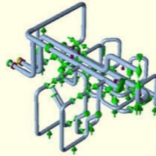
In this case study, a number of critical sections in an already installed fire water system were selected for review. At the time of the analysis, earlier on-site interventions had already been made, motivated by pipe failures. The analysis aimed to determine if additional interventions were necessary.
In this case study, a number of critical sections in an already installed fire water system were selected for review. At the time of the analysis, earlier on-site interventions had already been made, motivated by pipe failures. The analysis aimed to determine if additional interventions were necessary.
⬇️ Analysis
Based on the isometric drawings, a number of critical sections were identified and analyzed using the piping analysis software CAESAR II. A selection process revealed typical layouts and designs for these critical sections. An important aspect of the analysis was the sensitivity of the piping to settlements, especially of thrust blocks.
Based on the isometric drawings, a number of critical sections were identified and analyzed using the piping analysis software CAESAR II. A selection process revealed typical layouts and designs for these critical sections. An important aspect of the analysis was the sensitivity of the piping to settlements, especially of thrust blocks.
⬇️ Results
The analysis results showed that thrust blocks had been adequately sized concerning pressure thrust. Furthermore, it was observed that stress problems did not occur in piping that had been joined using coupling joints. For one critical section where coupling joints were used, the effect of settlement of thrust blocks was examined. It was concluded that piping with coupling joints is not sensitive to this problem due to the additional flexibility provided by the joints.
The analysis results showed that thrust blocks had been adequately sized concerning pressure thrust. Furthermore, it was observed that stress problems did not occur in piping that had been joined using coupling joints. For one critical section where coupling joints were used, the effect of settlement of thrust blocks was examined. It was concluded that piping with coupling joints is not sensitive to this problem due to the additional flexibility provided by the joints.