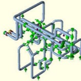
HANGER RODS
Vertical support that incorporates a rod. It may be a rigid, variable spring or constant support hanger.
Rod hangers or pipe hangers fixed to the pipe by a clevis, U bolt, a pipe clamp, etc.
The rod hanger gives support in the vertical direction and permits limited movement in the horizontal direction.
Vertical support that incorporates a rod. It may be a rigid, variable spring or constant support hanger.
Rod hangers or pipe hangers fixed to the pipe by a clevis, U bolt, a pipe clamp, etc.
The rod hanger gives support in the vertical direction and permits limited movement in the horizontal direction.
GUIDES
If restriction of pipe movement isn’t required, guides are used.
Pipe guides constrict movement along the pipe’s linear axis. This is called as a ‘sliding point’. Guides mainly used to maintain appropriate line spacing in a pipe rack and they restrict lateral or sideway movement.
Different than the pipe anchor, the guide permits pipe to slide.
If restriction of pipe movement isn’t required, guides are used.
Pipe guides constrict movement along the pipe’s linear axis. This is called as a ‘sliding point’. Guides mainly used to maintain appropriate line spacing in a pipe rack and they restrict lateral or sideway movement.
Different than the pipe anchor, the guide permits pipe to slide.
CONSTANT LOAD HANGER
A particularly engineered hanger that is designed to move through many inches of vertical movement with a minimal change in support load. There are different designs and types depending on the producers.
Constant hangers and constant supports are used when higher levels of vertical travel occur. Their function is to transfer the working load over the whole travel area while maintaining constancy, i.e., without any considerable deviations.
A particularly engineered hanger that is designed to move through many inches of vertical movement with a minimal change in support load. There are different designs and types depending on the producers.
Constant hangers and constant supports are used when higher levels of vertical travel occur. Their function is to transfer the working load over the whole travel area while maintaining constancy, i.e., without any considerable deviations.
VARIABLE SPRING HANGERS AND SUPPORTS
Helical coils that are used to support a dead weight load and allow movement. Spring supports use helical coil compression springs Helical Coil Compression is the critical component in both the type of spring supports
Helical coils that are used to support a dead weight load and allow movement. Spring supports use helical coil compression springs Helical Coil Compression is the critical component in both the type of spring supports
HYDRAULIC SHOCK ABSORBERS
Shock absorbers mostly preferred in piping systems that are thermally operating. In a dynamic event, the shock absorber forms a rigid restraint between the protected part and the structure. This way dynamic energy can be absorbed and harmlessly transferred.
Shock absorbers mostly preferred in piping systems that are thermally operating. In a dynamic event, the shock absorber forms a rigid restraint between the protected part and the structure. This way dynamic energy can be absorbed and harmlessly transferred.
Piping Stress Analysis (PSA Group)
Photo
What Is MSS SP-58?
MSS SP-58 is the set of guidelines and fabrication criteria for pipe hanger components to ensure pipes maintain the combined weight of the pipe system and the material that passes through it.
MSS SP-58 is the set of guidelines and fabrication criteria for pipe hanger components to ensure pipes maintain the combined weight of the pipe system and the material that passes through it.
ساپورت گذاری سیستم پایپینگ.pdf
16.9 MB
Share ساپورت گذاری سیستم پایپینگ.pdf
Fabrication of pipe supports requires attention. How the pipe supports are prefabricated and how they are installed is important. Wrong prefabrication/installation of pipe supports could cause unwanted effects (high repair costs, failure of the pipe support etc.). Pipe supports often contain a mix of metallic materials together with non-metallic components. The fabrication of such items requires good workmanship. It starts with a good design and fabrication friendly solutions/philosophies, but also the fabrication process has its challenges. It is very important to follow up both vendors of pipe support standard details and the main fabricator contractor to ensure good workmanship in all phases of the pipe support fabrication.
Installation weld Guide/Stop – Welding guides adjacent to e.g a pipe support shoe is a challenge. Because the guide-weld towards the shoe needs to be from one side, the type of weld to be used is a challenge. A full pen. weld is not possible if we want the intended function between the guide and the shoe base plate. A type of K-weld could be evaluated.
PIPE SUPPORT FRAMEWORK
The prefabrication of the pipe support frames usually follows the standard and procedures for structural steel. However pipe supports may have a different material philosophy (using stainless steel like 316L or Lean Duplex). In those cases we may use hollow sections with thin wall (due to higher strength). such sections, attention should be made to the places where partly penetration welds are used (ref. highlighted weld in fig.). When we have a section wall thickness less than 6mm we might come in conflict with minimum weld size requirements. This needs to be clarified before design/fabrication starts.
The prefabrication of the pipe support frames usually follows the standard and procedures for structural steel. However pipe supports may have a different material philosophy (using stainless steel like 316L or Lean Duplex). In those cases we may use hollow sections with thin wall (due to higher strength). such sections, attention should be made to the places where partly penetration welds are used (ref. highlighted weld in fig.). When we have a section wall thickness less than 6mm we might come in conflict with minimum weld size requirements. This needs to be clarified before design/fabrication starts.
Pipe Support Small Bore Connection ⬇️
A challenging task regarding pipe support design is supporting of small bore connections (SBC) with a lump mass at the end (e.g. pipe vent/drain, instruments connection etc.). With this article, Pipe Support Verification’s aim is to give the basic thoughts of doing a good SBC support design.
We can divide the supporting of SBC in two categories:
Static effects – meaning the lump mass needs supporting because of large static loads.
Dynamic effects – meaning vibrations in the SBC caused by flow induced vibration (FIV), acoustic induced vibration (AIV) or equipment induced vibration (EIV).
The most challenging is the supporting due to dynamic effects. To find the SBC that require bracing, we need to evaluate where it is likely that vibrations can occur. Regarding FIV, the piping stress group usually do a FIV screening to find the LOF parameter (likelihood of failure) for the pipe system. If this parameter is above the limit set for the project, bracing should be provided for all SBC in that system. A typical limit can be a LOF>0,5 for medium stiff system. In addition to FIV we need to evaluate other sources of vibrations such as AIV (typ. flare system) or EIV (Equipment that causes vibrations in connected pipe systems). This to find which SBC that need bracing.
When the SBC that need bracing has been concluded, the next question is how? There are several types of bracing. Clamped, Welded sections, welded plates (knee-braces) etc. How they are attached to the SBC does also vary.
A challenging task regarding pipe support design is supporting of small bore connections (SBC) with a lump mass at the end (e.g. pipe vent/drain, instruments connection etc.). With this article, Pipe Support Verification’s aim is to give the basic thoughts of doing a good SBC support design.
We can divide the supporting of SBC in two categories:
Static effects – meaning the lump mass needs supporting because of large static loads.
Dynamic effects – meaning vibrations in the SBC caused by flow induced vibration (FIV), acoustic induced vibration (AIV) or equipment induced vibration (EIV).
The most challenging is the supporting due to dynamic effects. To find the SBC that require bracing, we need to evaluate where it is likely that vibrations can occur. Regarding FIV, the piping stress group usually do a FIV screening to find the LOF parameter (likelihood of failure) for the pipe system. If this parameter is above the limit set for the project, bracing should be provided for all SBC in that system. A typical limit can be a LOF>0,5 for medium stiff system. In addition to FIV we need to evaluate other sources of vibrations such as AIV (typ. flare system) or EIV (Equipment that causes vibrations in connected pipe systems). This to find which SBC that need bracing.
When the SBC that need bracing has been concluded, the next question is how? There are several types of bracing. Clamped, Welded sections, welded plates (knee-braces) etc. How they are attached to the SBC does also vary.