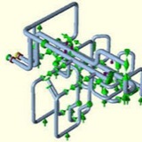
Stress analysis of a pump skid from storage towers to dual pumps. The temperature distribution of the piping varies depending on which pump or pumps are running. Here the pipes leading to the operating pump are hotter than the standby pipes. Multiple load cases are required to ensure the piping design is acceptable.
جزوه لوله کشی.pdf
783.3 KB
جزوه لوله کشی.pdf
Forwarded from Amir Hassimi
This media is not supported in your browser
VIEW IN TELEGRAM
Pipeline Repairing by using Smart Flange
Forwarded from Amir Hassimi
This media is not supported in your browser
VIEW IN TELEGRAM
قرار دادن یک شیر روی خط لوله درحال جریان
Forwarded from Piping Stress Analysis (PSA Group)
Forwarded from Piping Stress Analysis (PSA Group)
Forwarded from Piping Stress Analysis (PSA Group)
Piping Flexibility Thermal Expansion of Pipe
Abstract
One major requirement in piping design is to provide adequate flexibility for absorbing the thermal expansion of the pipe. However, due to lack of quick method of checking, pipings are often laid-out to be either too stiff or too flexible. In either case, valuable time and material are wasted.
This article presents some of the quick methods for checking piping flexibility. These methods include visual, hand calculation, and micro computer approaches. They are all quick and easy for designers to use in planning their layouts. Once the designers have taken care of the flexibility problem, the iterative procedure between the stress engineers and the designers become simpler. The project schedule can also be improved.
Abstract
One major requirement in piping design is to provide adequate flexibility for absorbing the thermal expansion of the pipe. However, due to lack of quick method of checking, pipings are often laid-out to be either too stiff or too flexible. In either case, valuable time and material are wasted.
This article presents some of the quick methods for checking piping flexibility. These methods include visual, hand calculation, and micro computer approaches. They are all quick and easy for designers to use in planning their layouts. Once the designers have taken care of the flexibility problem, the iterative procedure between the stress engineers and the designers become simpler. The project schedule can also be improved.
Piping flexibility
As the pipe temperature changes from the installation condition to the operating condition, it expands or contracts. In the general term, both expansion and contraction are called thermal expansion. When a pipe expands it has the potential of generating enormous force and stress in the system. However, if the piping is flexible enough, the expansion can be absorbed without creating undue force or stress. Providing the proper flexibility is one of the major tasks in the design of piping system.
Piping is used to convey a certain amount of fluid from one point to another. It is obvious that the shorter the pipe is used the lesser the capital expenditure is required. The long pipe may also generate excessive pressure drop making it unsuitable for the proper operation. However, the direct shortest layout generally is not acceptable for absorbing the thermal expansion.
Figure 1 shows what will happen when a straight pipe is directly connected from one point to another. First, consider that only one end is connected and the other end is loose. The loose end will expands an amount equal to Δ = e L
However, since the other end is not loose, this expansion is to be absorbed by the piping. This is equivalent to squeezing the pipe to move the end back an ~ distance. This amount of squczzing creates a stress of the magnitude S = E (Δ/L) = E e
As the pipe temperature changes from the installation condition to the operating condition, it expands or contracts. In the general term, both expansion and contraction are called thermal expansion. When a pipe expands it has the potential of generating enormous force and stress in the system. However, if the piping is flexible enough, the expansion can be absorbed without creating undue force or stress. Providing the proper flexibility is one of the major tasks in the design of piping system.
Piping is used to convey a certain amount of fluid from one point to another. It is obvious that the shorter the pipe is used the lesser the capital expenditure is required. The long pipe may also generate excessive pressure drop making it unsuitable for the proper operation. However, the direct shortest layout generally is not acceptable for absorbing the thermal expansion.
Figure 1 shows what will happen when a straight pipe is directly connected from one point to another. First, consider that only one end is connected and the other end is loose. The loose end will expands an amount equal to Δ = e L
However, since the other end is not loose, this expansion is to be absorbed by the piping. This is equivalent to squeezing the pipe to move the end back an ~ distance. This amount of squczzing creates a stress of the magnitude S = E (Δ/L) = E e
The force required to squeeze this amount is F = A S = A E e
Take a 6-inch standard wall carbon steel pipe for instance, an increase of temperature from 70F ambient to 300F operating creates an axial stress of 42300 psi and an axial force of 236000 lbs in the pipe. These are excessive even though the temperature is only 300F. It is clear that the straight line direct layout is not acceptable to most of the piping, Flexibility has to be provided.
Expansion loop
Piping flexibility are provided in many different ways. The turns and offsets needed for running the pipe from one point to another provides some flexibility by themself. This inherent flexibility may or may not be sufficient depending on the individual cases.
Additional flexibility can be provided by adding expansion loops or expansion joints. In the straight line example discussed above, the stress can be reduced by loops installed as shown below. The idea is to provide some pipe perpendicular to the direction of expansion. In this way when the pipe expands it bends the loop leg first before transmitting any load to the anchor. The longer the loop leg the lesser the force will be created.
Piping flexibility are provided in many different ways. The turns and offsets needed for running the pipe from one point to another provides some flexibility by themself. This inherent flexibility may or may not be sufficient depending on the individual cases.
Additional flexibility can be provided by adding expansion loops or expansion joints. In the straight line example discussed above, the stress can be reduced by loops installed as shown below. The idea is to provide some pipe perpendicular to the direction of expansion. In this way when the pipe expands it bends the loop leg first before transmitting any load to the anchor. The longer the loop leg the lesser the force will be created.
The force created is inversely proportional to the cube of the loop length and the stress generated is roughly Hard Piping inversely proportional to the square of the loop length. The loop sometimes can take considerably more space and piping than what is available, or economically justifiable. This is especially true for large high temperature low pressure pipings.
In this case the better method is to use expansion joint. Expansion joints are more sophisticated than the pipe loops which are just extra lengths of the same piping. For this and other reasons, engineers tend to favor piping loops over expansion joints.
However, expansion joints can be used effectively in many applications when they are properly designed. One of the major requirements in the design of expansion joint system is to install sufficient restraints for maintaining the stability. This article deals mainly the loop approach.
In this case the better method is to use expansion joint. Expansion joints are more sophisticated than the pipe loops which are just extra lengths of the same piping. For this and other reasons, engineers tend to favor piping loops over expansion joints.
However, expansion joints can be used effectively in many applications when they are properly designed. One of the major requirements in the design of expansion joint system is to install sufficient restraints for maintaining the stability. This article deals mainly the loop approach.
The Critical Path❗️
In designing a plant, the piping is generally routed or laid-out by the piping designers then checked by the stress engineers.
There is a marked difference in the layout done by the experienced and the inexperienced designers. The experienced designers know the importance of the flexibility. However, they tend to provide too much flexibility in contrast to the inexperienced ones who tend to provide little flexibility. In either case, the resulL is an over priced project.
The layout done by an inexperienced designer is normally too stiff because the designer does not know how or too timid to add loops or offsets. If a piping system is too stiff, the stress engineer will almost certain to find it out.
The stress engineer will send the design, with recommended loops, back to the designer for revision. At this time, the designer have made some more layouts in the same area making the revision very difficulty. On the other hand, a layout done by an experienced designer often contains the loops which are excessive or not needed.
The excessive loops are normally maintained without revision, becuase it is a common prctice not to change something which works. The experienced one might have saved the manhour needed for the revision. The cost of the excessive loops can be prohibitive.
In designing a plant, the piping is generally routed or laid-out by the piping designers then checked by the stress engineers.
There is a marked difference in the layout done by the experienced and the inexperienced designers. The experienced designers know the importance of the flexibility. However, they tend to provide too much flexibility in contrast to the inexperienced ones who tend to provide little flexibility. In either case, the resulL is an over priced project.
The layout done by an inexperienced designer is normally too stiff because the designer does not know how or too timid to add loops or offsets. If a piping system is too stiff, the stress engineer will almost certain to find it out.
The stress engineer will send the design, with recommended loops, back to the designer for revision. At this time, the designer have made some more layouts in the same area making the revision very difficulty. On the other hand, a layout done by an experienced designer often contains the loops which are excessive or not needed.
The excessive loops are normally maintained without revision, becuase it is a common prctice not to change something which works. The experienced one might have saved the manhour needed for the revision. The cost of the excessive loops can be prohibitive.
animation.gif
4 KB
Where,
Δ = thermal expansion, in
L e = expansion rate, in/in
L = pipe length, in
s = axial stress, psi
F E = modulus of elasticity, psi
A = pipe cross section area, inZ
F = axial force, lbs
Δ = thermal expansion, in
L e = expansion rate, in/in
L = pipe length, in
s = axial stress, psi
F E = modulus of elasticity, psi
A = pipe cross section area, inZ
F = axial force, lbs