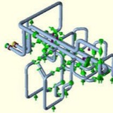
3. Hot Sustained Check Philosophy from Caesar II 2018 version onwards:
From Caesar II version 2016 onwards, based on code requirements they have created a load case type known as ALT-SUS. So, in the single file, by adding ALT-SUS load cases, Caesar II automatically calculates hot-sustained stresses for each operating condition. Refer to Fig. 3 below to understand the load cases which has been introduced from ASME B 31.3-2014 onwards as Alternate sustained stress checking.
From Caesar II version 2016 onwards, based on code requirements they have created a load case type known as ALT-SUS. So, in the single file, by adding ALT-SUS load cases, Caesar II automatically calculates hot-sustained stresses for each operating condition. Refer to Fig. 3 below to understand the load cases which has been introduced from ASME B 31.3-2014 onwards as Alternate sustained stress checking.
So, the above stresses are sufficient for hot-sustained stress checking. Load case L3 is checking sustained stress for temperature T1; which means in load case L3 all supports which are lifting or not taking load will be removed by the software automatically and sustained stress will be calculated after that. Similar situation will arise for load case L5 and L7 as shown above and they are the hot sustained cases with respect to temperature case T2 and T3 respectively.
Notes:
1- Now you may be thinking whether to mark deleted supports in isometric or not. You must mark those supports. As we have not deleted the supports in actual practice. Supports will be there at site, We simply ensured that without those supports also system will be safe. However if you want to delete those supports that can be done if all other stress criteria can met.
2-Whether we need to check expansion stresses in hot sustained file too? In my opinion if we are using liberal stress for expansion stress range checking then it is better to check expansion stress (along with sustained stress) in hot sustained file. Otherwise it is not required as system won’t fail in expansion case even after removing those supports.
1- Now you may be thinking whether to mark deleted supports in isometric or not. You must mark those supports. As we have not deleted the supports in actual practice. Supports will be there at site, We simply ensured that without those supports also system will be safe. However if you want to delete those supports that can be done if all other stress criteria can met.
2-Whether we need to check expansion stresses in hot sustained file too? In my opinion if we are using liberal stress for expansion stress range checking then it is better to check expansion stress (along with sustained stress) in hot sustained file. Otherwise it is not required as system won’t fail in expansion case even after removing those supports.
Piping Stress Analysis (PSA Group) pinned «Hot Sustained Stress (Lift-Off) Checking in Caesar II»
animation.gif
66 KB
HOW DO SNUBBER SUPPORTS WORK IN DYNAMIC CONDITIONS
⬆️ Snubbers are activated when either a threshold acceleration (hydraulic snubbers) or threshold velocity (mechanical snubbers) is reached. At that point, the snubber is activated either via a valve system (hydraulic snubbers) or spring loaded mechanical stop (mechanical snubbers) to lock in position and act as a restraint device to prevent further movement of the pipeline.
Momentum Technologies provides a high frequency tuned mass damper; the Momentum TMD. It is a state-of-the-art product for mitigating resonance vibration above 20Hz. These unique characteristics makes the Momentum TMD very suitable for solving vibration problems in small bore gas piping and machinery piping.
Momentum TMD – INSTALLATION
The Momentum TMD is clamped to the pipe or structure to be damped, with the integrated clamp included in the delivery. The mounting can be made during operation and no hot work is needed for the installation. The Momentum TMD is free hanging and do not need any support or other foundation.
The mono-clamp design enables the damper to be fitted to pipes at various locations, for example close to bends. Momentum Technologies do also provide customized clamp or attachement solutions, for example brackets suitable for installation at valve flanges.
The Momentum TMD is clamped to the pipe or structure to be damped, with the integrated clamp included in the delivery. The mounting can be made during operation and no hot work is needed for the installation. The Momentum TMD is free hanging and do not need any support or other foundation.
The mono-clamp design enables the damper to be fitted to pipes at various locations, for example close to bends. Momentum Technologies do also provide customized clamp or attachement solutions, for example brackets suitable for installation at valve flanges.
This media is not supported in your browser
VIEW IN TELEGRAM
Heat Exchanger Animation
Piping designers traditionally route piping by layout, process, flow constraints (such as pressure drop) and other constraints but often do not take vibratory service into consideration. Pipe stresses are often not sufficiently considered while routing and supporting dynamics piping systems, especially when providing adequate flexibility to absorb thermal expansion/contraction of pipes. Upon completion of this analysis, Compression Dynamics will present you with proper modifications to bring piping systems into API or ASME codes.
A tower with a guided flexible pipe connection. The guided connection allows the flexibility required in the nozzle while limiting the loads applied to the vessel nozzle. Modelling the flexibility of the nozzle and accounting for the different possible temperatures of the piping system and tower is required for successful analysis.