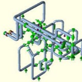
Pipe support design
The supports shall be designed to meet all static and operational conditions to
which the piping system and connected equipment will be subjected. These
conditions shall include hydrostatic test loadings, thermal expansion and
contraction, seismic shock loading, impact, vibration, overloading, spring failure,
erection loading, pressure thrust and fluid momentum (for open discharge
systems), and (for out-door locations) wind, snow, and ice loadings. Code,
seismic and safety classifications, and other necessary data will be defined in the
Project Specification. For supports specified to be designed in accordance with
ASME B31.1, the loads should not be based on increasing the allowable stress
level in hanger components by 20%, as allowed for piping in Paragraph
121.1.2.A.1 of the code.
The supports shall be designed to meet all static and operational conditions to
which the piping system and connected equipment will be subjected. These
conditions shall include hydrostatic test loadings, thermal expansion and
contraction, seismic shock loading, impact, vibration, overloading, spring failure,
erection loading, pressure thrust and fluid momentum (for open discharge
systems), and (for out-door locations) wind, snow, and ice loadings. Code,
seismic and safety classifications, and other necessary data will be defined in the
Project Specification. For supports specified to be designed in accordance with
ASME B31.1, the loads should not be based on increasing the allowable stress
level in hanger components by 20%, as allowed for piping in Paragraph
121.1.2.A.1 of the code.
The materials and fabrication of all supports that are to be furnished by Contractor
and that are detailed on the Purchaser drawings shall be in strict conformance
with such details. However, Contractor shall check design data furnished to him
and shall indicate on the drawings returned to the Purchaser all modifications
recommended by the Contractor. Contractor shall fill in the bill of material
tabulation in the spaces provided, indicating weight of support, correct total
loading, and any/all other necessary data, where not complete by the Purchaser.
and that are detailed on the Purchaser drawings shall be in strict conformance
with such details. However, Contractor shall check design data furnished to him
and shall indicate on the drawings returned to the Purchaser all modifications
recommended by the Contractor. Contractor shall fill in the bill of material
tabulation in the spaces provided, indicating weight of support, correct total
loading, and any/all other necessary data, where not complete by the Purchaser.
Where supports are not designed and detailed by the Purchaser, Contractor's
supports designer shall analyze and determine the piping loads and movements
that will exist ay any time, including all applicable forces acting simultaneously,
and shall design and detail the supports in accordance therewith. The
temperature of piping to be used in the design of supports therefore will be
indicated in Field (Column) 4 of the Piping Line List (if Piping Line List is included
as a part of the Project Specification) or will be indicated in the Project
Specification. Consideration of piping movements shall not be made before the
maximum temperature of such piping is indicated.
supports designer shall analyze and determine the piping loads and movements
that will exist ay any time, including all applicable forces acting simultaneously,
and shall design and detail the supports in accordance therewith. The
temperature of piping to be used in the design of supports therefore will be
indicated in Field (Column) 4 of the Piping Line List (if Piping Line List is included
as a part of the Project Specification) or will be indicated in the Project
Specification. Consideration of piping movements shall not be made before the
maximum temperature of such piping is indicated.
Where special wall piping is involved, supports for same shall not be released for fabrication until the actual dimensions and weights of such piping have been determined and listed in the Project Specification or on the drawings. Dimensions and weights of special wall piping listed in the Project Specification or on the drawings are actual, unless specifically noted otherwise.
The type and thickness of insulation will be indicated in material list (bill of material). The thickness given is nominal and includes the insulation jacket or covering which shall be assumed to be negligible unless otherwise noted. The weight of the insulation will be indicated in the Project Specification and/or drawings and is a nominal figure for the insulation and jacket or covering, unless otherwise noted. Release of supports for fabrication shall not be done before the thickness and weight of insulation are indicated.
As a general guideline, Contractor shall strive for a minimum clearance of approximately 6 in., as far as practical, for all system in both hot and cold positions between supports and any obstructions. For systems where thermal growth will occur, sufficient clearance shall be provided to prevent interference between supports and surrounding equipment during this growth.
This media is not supported in your browser
VIEW IN TELEGRAM
Video from Akbar Daneshvar
Forwarded from Akbar Daneshvar
Media is too big
VIEW IN TELEGRAM
شرکت راهبرد انرژی پسا
تولید انواع ساپورت های کلمپی خاص
تولید انواع ساپورت های کلمپی خاص
Forwarded from Akbar Daneshvar
This media is not supported in your browser
VIEW IN TELEGRAM
شرکت راهبرد انرژی پسا
تولید ساپورت های غلتکی برای صنایع فولاد، معدنی، و کارخانجات مواد غذایی
تولید ساپورت های غلتکی برای صنایع فولاد، معدنی، و کارخانجات مواد غذایی
This media is not supported in your browser
VIEW IN TELEGRAM
شرکت راهبرد انرژی پسا
APPLICATION: Adjustable Pipe Roller and Stand is used to support piping where 1.) significant movement along the axis of the piping at the support location occurs due to thermal expansion or contraction of the piping, 2.) support is to be provided from a beam or other structural member located below the piping and 3.) vertical adjustment of the pipe roll is necessary and relatively easy to accomplish. This Adjustable Pipe Roller and Stand allows axial movement of the piping with virtually a negligible amount of frictional resistance to the movement. Vertical adjustment is achieved by turning the adjustment bolts up or down on the base. Adjustable Pipe Roller and Stand is designed to be bolted or welded to the supporting structural members.
Pipe Spiders & Rollers
In many infrastructure projects, one or more pipes are installed inside a larger concrete or steel pipe. The installation of the internal pipes is effective as well as efficient with Anchorage Pipe Spiders. They are commonly used in micro tunneling, pipe jacking and water applications. Other applications include heat shields for steam piping, conduit enclosure, heat exchanges and thermal insulation.
In many infrastructure projects, one or more pipes are installed inside a larger concrete or steel pipe. The installation of the internal pipes is effective as well as efficient with Anchorage Pipe Spiders. They are commonly used in micro tunneling, pipe jacking and water applications. Other applications include heat shields for steam piping, conduit enclosure, heat exchanges and thermal insulation.
Hot Sustained Stress (Lift-Off) Checking in Caesar II
In Layman’s term Sustained means always present. So sustained stresses are the stresses which are present in the system throughout its operating cycle. The weight of the piping system and Pressure inside the pipe are examples of sustained loads that generate sustained stresses in the system. So what is a hot sustained case?
While analyzing a piping system you many times will come across with few supports which will take load in sustained case but are not taking load in operating and design temperature cases (Refer Attached Fig. 1 and Fig. 2 for one such typical example). The support is lifting at that point in temperature case i.e. supports are not contributing in load and stress distribution while in in operating condition. Still in that situation the weight of pipe and pressure inside the system will induce sustained stresses. So in my opinion, hot sustained stress is the sustained stress in pipe operating situation. And we must ensure that the system stress will not fail because of those supports not sharing any load. That is why many organization make it mandatory to check sustained stresses.
Methods of Hot Sustained stress checking
I have come across two different methods of hot sustained stress check in the various organization based on old philosophy:
I have come across two different methods of hot sustained stress check in the various organization based on old philosophy:
1. Conventional Method of Hot Sustained Check
In first method the analyst has to run the static analysis as per conventional method.
Now go to restraint summary and note down the support nodes which are lifting or not taking any vertical load (Sometimes small positive value may be there due to guide and line stop frictions, in that case check the vertical displacement if it shows positive value consider the same as lifting).
Make a separate Caesar file with name FILE NAME_HOT SUSTAINED.
Open the input screen and delete all lifting supports from the nodes you noted down. Delete only +Y support, Guide and line stops will be there.
Run the analysis and check sustained stress.
If sustained stress is within allowable limit accept the file as it is else change the support location or routing to make the system safe.
In first method the analyst has to run the static analysis as per conventional method.
Now go to restraint summary and note down the support nodes which are lifting or not taking any vertical load (Sometimes small positive value may be there due to guide and line stop frictions, in that case check the vertical displacement if it shows positive value consider the same as lifting).
Make a separate Caesar file with name FILE NAME_HOT SUSTAINED.
Open the input screen and delete all lifting supports from the nodes you noted down. Delete only +Y support, Guide and line stops will be there.
Run the analysis and check sustained stress.
If sustained stress is within allowable limit accept the file as it is else change the support location or routing to make the system safe.
This media is not supported in your browser
VIEW IN TELEGRAM