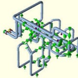
⬇️⬇️ Jacketed Pipe
Jacketed piping can be idealized as two piping systems running along coincident lines in space. The two piping systems are of two different sizes, so the smaller runs inside of the larger. The internal pipe contains the piped fluid, while the outer pipe (the jacket) is used for protection or to carry a heated fluid to warm that in the inner pipe.
Jacketed piping can be idealized as two piping systems running along coincident lines in space. The two piping systems are of two different sizes, so the smaller runs inside of the larger. The internal pipe contains the piped fluid, while the outer pipe (the jacket) is used for protection or to carry a heated fluid to warm that in the inner pipe.
Jacketed piping systems are modeled by running the jacket elements directly on top of the core elements where the two are concentric. Internal supports (spiders) offer negligible resistance to relative bending and axial displacement, so rigid restraints should be placed between the inner and outer pipe (for example between node points 15 and 1015) only in the local Y- and Z-directions. The end caps connecting the core to the jacket of the pipe are usually much stiffer than either the core or the jacket. For this reason at end cap locations (node points 10 and 25), the inner and outer pipes should share the same node point (i.e., node points 1010 and 1025 should not be used) — this ensures that the rotations and displacements are identical for the two pipes at these locations.
The +Y support acting on the jacket at node point 1020 does not cause any restraint to be inserted between nodes 20 and 1020. Node 20 is included in the model so that interference with the outside diameter can be checked at the 20-1020 cross section. Should there be concerns about interference, a restraint with a gap equal to the clearance between the inner and outer pipes can be entered. If a load develops at that restraint, this indicates an interference.
The +Y support acting on the jacket at node point 1020 does not cause any restraint to be inserted between nodes 20 and 1020. Node 20 is included in the model so that interference with the outside diameter can be checked at the 20-1020 cross section. Should there be concerns about interference, a restraint with a gap equal to the clearance between the inner and outer pipes can be entered. If a load develops at that restraint, this indicates an interference.
The specific modeling process is fairly simple. The inner pipe is modeled first, with the user taking care to place a node point at each location where there is an internal spacer support. Next the inner pipe is duplicated using the element block copy feature (accessed with the List hot key from the input spreadsheet). The entire run of the inner pipe should be copied, with a suitable node increment to ensure that no nodes are duplicated between the two copies.
The second copy becomes the outer pipe. It is necessary to first change the diameter and wall thickness (and possibly the fluid density and temperature) of the pipe on the first screen of the outer pipe; these changes propagate through. Next the user must go through and change the bend radii of each of the elbows in the outer pipe. The first and last node numbers of the outer pipe should then be changed to the same node numbers as those of the first and last point of the inner point — this serves to connect the inner to the outer pipe, a fact that can be confirmed by using CAESAR II's PLOT option.
Finally, the internal supports are modeled by placing guides (and vertical supports on horizontal runs) at each of the support points on the inner pipe, with CNODES to the corresponding points on the outer pipe. Any pipe restraints are then placed on the outer pipe only.
Pipe support design
The supports shall be designed to meet all static and operational conditions to
which the piping system and connected equipment will be subjected. These
conditions shall include hydrostatic test loadings, thermal expansion and
contraction, seismic shock loading, impact, vibration, overloading, spring failure,
erection loading, pressure thrust and fluid momentum (for open discharge
systems), and (for out-door locations) wind, snow, and ice loadings. Code,
seismic and safety classifications, and other necessary data will be defined in the
Project Specification. For supports specified to be designed in accordance with
ASME B31.1, the loads should not be based on increasing the allowable stress
level in hanger components by 20%, as allowed for piping in Paragraph
121.1.2.A.1 of the code.
The supports shall be designed to meet all static and operational conditions to
which the piping system and connected equipment will be subjected. These
conditions shall include hydrostatic test loadings, thermal expansion and
contraction, seismic shock loading, impact, vibration, overloading, spring failure,
erection loading, pressure thrust and fluid momentum (for open discharge
systems), and (for out-door locations) wind, snow, and ice loadings. Code,
seismic and safety classifications, and other necessary data will be defined in the
Project Specification. For supports specified to be designed in accordance with
ASME B31.1, the loads should not be based on increasing the allowable stress
level in hanger components by 20%, as allowed for piping in Paragraph
121.1.2.A.1 of the code.
The materials and fabrication of all supports that are to be furnished by Contractor
and that are detailed on the Purchaser drawings shall be in strict conformance
with such details. However, Contractor shall check design data furnished to him
and shall indicate on the drawings returned to the Purchaser all modifications
recommended by the Contractor. Contractor shall fill in the bill of material
tabulation in the spaces provided, indicating weight of support, correct total
loading, and any/all other necessary data, where not complete by the Purchaser.
and that are detailed on the Purchaser drawings shall be in strict conformance
with such details. However, Contractor shall check design data furnished to him
and shall indicate on the drawings returned to the Purchaser all modifications
recommended by the Contractor. Contractor shall fill in the bill of material
tabulation in the spaces provided, indicating weight of support, correct total
loading, and any/all other necessary data, where not complete by the Purchaser.
Where supports are not designed and detailed by the Purchaser, Contractor's
supports designer shall analyze and determine the piping loads and movements
that will exist ay any time, including all applicable forces acting simultaneously,
and shall design and detail the supports in accordance therewith. The
temperature of piping to be used in the design of supports therefore will be
indicated in Field (Column) 4 of the Piping Line List (if Piping Line List is included
as a part of the Project Specification) or will be indicated in the Project
Specification. Consideration of piping movements shall not be made before the
maximum temperature of such piping is indicated.
supports designer shall analyze and determine the piping loads and movements
that will exist ay any time, including all applicable forces acting simultaneously,
and shall design and detail the supports in accordance therewith. The
temperature of piping to be used in the design of supports therefore will be
indicated in Field (Column) 4 of the Piping Line List (if Piping Line List is included
as a part of the Project Specification) or will be indicated in the Project
Specification. Consideration of piping movements shall not be made before the
maximum temperature of such piping is indicated.
Where special wall piping is involved, supports for same shall not be released for fabrication until the actual dimensions and weights of such piping have been determined and listed in the Project Specification or on the drawings. Dimensions and weights of special wall piping listed in the Project Specification or on the drawings are actual, unless specifically noted otherwise.
The type and thickness of insulation will be indicated in material list (bill of material). The thickness given is nominal and includes the insulation jacket or covering which shall be assumed to be negligible unless otherwise noted. The weight of the insulation will be indicated in the Project Specification and/or drawings and is a nominal figure for the insulation and jacket or covering, unless otherwise noted. Release of supports for fabrication shall not be done before the thickness and weight of insulation are indicated.
As a general guideline, Contractor shall strive for a minimum clearance of approximately 6 in., as far as practical, for all system in both hot and cold positions between supports and any obstructions. For systems where thermal growth will occur, sufficient clearance shall be provided to prevent interference between supports and surrounding equipment during this growth.
This media is not supported in your browser
VIEW IN TELEGRAM
Video from Akbar Daneshvar
Forwarded from Akbar Daneshvar
Media is too big
VIEW IN TELEGRAM
شرکت راهبرد انرژی پسا
تولید انواع ساپورت های کلمپی خاص
تولید انواع ساپورت های کلمپی خاص
Forwarded from Akbar Daneshvar
This media is not supported in your browser
VIEW IN TELEGRAM
شرکت راهبرد انرژی پسا
تولید ساپورت های غلتکی برای صنایع فولاد، معدنی، و کارخانجات مواد غذایی
تولید ساپورت های غلتکی برای صنایع فولاد، معدنی، و کارخانجات مواد غذایی
This media is not supported in your browser
VIEW IN TELEGRAM
شرکت راهبرد انرژی پسا
APPLICATION: Adjustable Pipe Roller and Stand is used to support piping where 1.) significant movement along the axis of the piping at the support location occurs due to thermal expansion or contraction of the piping, 2.) support is to be provided from a beam or other structural member located below the piping and 3.) vertical adjustment of the pipe roll is necessary and relatively easy to accomplish. This Adjustable Pipe Roller and Stand allows axial movement of the piping with virtually a negligible amount of frictional resistance to the movement. Vertical adjustment is achieved by turning the adjustment bolts up or down on the base. Adjustable Pipe Roller and Stand is designed to be bolted or welded to the supporting structural members.
Pipe Spiders & Rollers
In many infrastructure projects, one or more pipes are installed inside a larger concrete or steel pipe. The installation of the internal pipes is effective as well as efficient with Anchorage Pipe Spiders. They are commonly used in micro tunneling, pipe jacking and water applications. Other applications include heat shields for steam piping, conduit enclosure, heat exchanges and thermal insulation.
In many infrastructure projects, one or more pipes are installed inside a larger concrete or steel pipe. The installation of the internal pipes is effective as well as efficient with Anchorage Pipe Spiders. They are commonly used in micro tunneling, pipe jacking and water applications. Other applications include heat shields for steam piping, conduit enclosure, heat exchanges and thermal insulation.
Hot Sustained Stress (Lift-Off) Checking in Caesar II