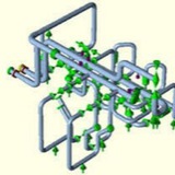
Answer:
Use the same modeling technique as used in the following AutoPIPE help section:
Help > Contents> Contents Tab> Modeling Approaches> Modeling Approaches> Vessels
In this case you will need to provide the DX, DY, and DZ. to both Pipe #1 and Pipe #2 connection locations.
Procedure:
1. Move cursor to header pipe node point (ex. A05)
2. Convert Node into a Tee
3. Insert new branch segment (ex. B) on tee (ex. from A05), extend new piping to Pipe #1 connection location (ex. B01), should be on the outside surface of the header pipe.
4. Insert additional node points on segment piping as needed.
5. Select the piping inside of the header pipe (ex. A05 to B01). Insert> Rigid Options Over Range> Include Weight - OFF, Include Thermal Expansion - ON. press OK button to close dialog screen.
6. Select the header node point, Insert Xtra Data> Joint type and user SIF = user defined, "Override all SIF's at this point" - Checked ON.
Use the same modeling technique as used in the following AutoPIPE help section:
Help > Contents> Contents Tab> Modeling Approaches> Modeling Approaches> Vessels
In this case you will need to provide the DX, DY, and DZ. to both Pipe #1 and Pipe #2 connection locations.
Procedure:
1. Move cursor to header pipe node point (ex. A05)
2. Convert Node into a Tee
3. Insert new branch segment (ex. B) on tee (ex. from A05), extend new piping to Pipe #1 connection location (ex. B01), should be on the outside surface of the header pipe.
4. Insert additional node points on segment piping as needed.
5. Select the piping inside of the header pipe (ex. A05 to B01). Insert> Rigid Options Over Range> Include Weight - OFF, Include Thermal Expansion - ON. press OK button to close dialog screen.
6. Select the header node point, Insert Xtra Data> Joint type and user SIF = user defined, "Override all SIF's at this point" - Checked ON.
7. Select node point on surface of pipe where the connection is made, (ex. B01), Insert Xtra Data> Joint type and user SIF, enter the correct SIF for the connection point, and again, "Override all SIF's at this point" - Checked ON.
8. Repeat steps #3 - #7 for each additional pipe to be connected at the same location (ex. A05).
9. Move to next header node point and repeat steps #1 - #8 for all points allong the header to have more that 1 pipe connection that is offset from the normal position.
8. Repeat steps #3 - #7 for each additional pipe to be connected at the same location (ex. A05).
9. Move to next header node point and repeat steps #1 - #8 for all points allong the header to have more that 1 pipe connection that is offset from the normal position.
Pipe Stress Analysis
PSA Piping performs Pipe Stress Analysis based on ASME codes (American Boiler and Pressure vessel). ASME codes cover the design, analysis, manufacturing and inspection of pressure vessels, piping and supporting structures. It represents a complete set of rules for the analysis of the mechanical components too.
PSA Piping performs Pipe Stress Analysis based on ASME codes (American Boiler and Pressure vessel). ASME codes cover the design, analysis, manufacturing and inspection of pressure vessels, piping and supporting structures. It represents a complete set of rules for the analysis of the mechanical components too.
PSA perform pipe stress analysis for the various load conditions such as:
1.Normal Operating
2.ConditionsUpset
3.ConditionsEmergency
4.ConditionsFaulted Conditions
1.Normal Operating
2.ConditionsUpset
3.ConditionsEmergency
4.ConditionsFaulted Conditions
We follow ASME B31 standard in the piping design and engineering for power and process plants and industrial and commercial facilities under very different loading conditions like as weight, thermal, seismic and other dynamic loads. PSA Piping uses ASME section III codes and NRC regulations in piping design of power plants.
We perform static analysis for the following loading conditions:
Pressure:
Operating pressure or upset condition pressures.
Operating pressure or upset condition pressures.
Deadweight:
This loading condition consists of the weight of pipe, medium, insulation and any attachment to the pipelines.
This loading condition consists of the weight of pipe, medium, insulation and any attachment to the pipelines.
Wind Loads:
This loading condition is a dynamic condition but normally analysed as equivalent static condition.
This loading condition is a dynamic condition but normally analysed as equivalent static condition.
Thermal Loads:
This loading condition is induced by different thermal transients.
This loading condition is induced by different thermal transients.