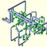
- Stability analysis:
We perform stability analysis on pressure vessels, piping systems and supporting structures, utilizing finite element analysis.
We perform stability analysis on pressure vessels, piping systems and supporting structures, utilizing finite element analysis.
Slug Flow Analysis:
slug flow analysis using dynamic methods.
slug flow analysis using dynamic methods.
For dynamic analysis Caesar II software provides a very nice module, dynamic module where we have to simply provide the input parameters to get the output result. Before you start the dynamic analysis you have to perform conventional static analysis of the system (without using any slug force) and qualify the system from all criteria. To open the dynamic module in Caesar II click on dynamic analysis button as shown in Fig.1.
When you click on the dynamic analysis button following window (Fig.2) will open. Select Slug Flow (Spectrum) from drop down menu. The window will be filled with some pre-existing data. For clarity simply select all those and delete. Now we have to provide inputs for analysis.
During dynamic analysis our first input will be the generation of spectrum profile. Slug load is one type of impulse load. So the magnitude of load varies from zero to some maximum value, remains constant for a time and then reduces to zero again. The force profile can be represented by a curve as shown in Fig. 3.
So from the above profile it is clear that in addition to slug force (Refer Static method of Slug Flow using Caesar II for calculation of slug force), we need to calculate two additional parameters,
a) Slug Duration and
b) Slug Periodicity.
a) Slug Duration and
b) Slug Periodicity.
Slug Duration:
Slug duration is defined as the time required for the slug to cross the elbow. Mathematically it can be denoted as, Slug Duration=Length of Liquid Slug/Velocity of Flow.
Slug duration is defined as the time required for the slug to cross the elbow. Mathematically it can be denoted as, Slug Duration=Length of Liquid Slug/Velocity of Flow.
Slug Periodicity:
Slug Periodicity can be defined as the time interval for two consecutive slugs hitting the same elbow. So mathematically it can be denoted as, Slug Periodicity = (Length of Liquid Slug + Length of Gas Slug)/Velocity of Flow.
Slug Periodicity can be defined as the time interval for two consecutive slugs hitting the same elbow. So mathematically it can be denoted as, Slug Periodicity = (Length of Liquid Slug + Length of Gas Slug)/Velocity of Flow.
Let’s assume that the calculated slug duration is 8 milliseconds and periodicity is 400 milliseconds as shown in Fig. 3. We will use these data for generation of spectrum profile.
Now Refer Fig. 4 and input the data as mentioned below:
When you click on Enter Pulse data it will open the window where we have to enter the data for spectrum profile generation. From the above curve at time 0 the force is 2120 N the same force will be active for next 8 milliseconds till the slug crosses the elbow. Then at time 8.1 forces will be reduced to zero. And the same zero force will be there till 400 milliseconds. Then the next cycle will start. i.e, at time 400.1 seconds the force will be again 2120 N. That way enters data for at least two cycles as shown in Fig. 5:
Points to consider while checking a stress system using Caesar II:
In most of the organization there is a 3 tier process for every stress system for maintaining quality of analyzed stress systems. Normally stress system is performed by one (junior or senior), checked by some other (must be experienced enough) and finally approved by the lead stress engineer. Even though the main points which need to be considered is well-known to every piping stress engineers, but still some important points could be missed at the specific moments during stress analysis or checking. So a checklist can be prepared and referred during the process for proper quality control. The following article will provide an insight of the main points which a stress engineer must check during analyzing a system. Request you to inform me additional points which i may have missed while writing this article by replying in comments section.
Important points to consider while checking any stress system:
1. Whether the input for pipe material, pipe diameter, pipe wall thickness, pipe temperatures (operating, design and upset), pressures (design and hydrotest), insulation thickness, corrosion allowance, fluid density, insulation density is correct?