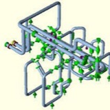
Figure 3 shows the weightless thermal case L3 with the addition of hold down restraints at every support except the one that lifts off. Note the similarity to Figure 1, the operating case.
You might object to this method because the hold-down supports aren’t actually there, but the hold-downs simply linearise the analysis and ensure that the assessment is not penalised for supports which do not in fact lift off. Sure, a support may only just be resting and we’re ignoring the portion of stress due to weight transfer away from that support. This aspect is discussed in more detail in the CAESAR II manual, but in my interpretation of the Code it does not matter. The state of physical contact with the support prevents further detrimental effect on the pipe, which is reflective of a secondary stress (self-limiting) rather than primary.
As seen in the table, for this particular model the difference between methods is huge (nb. the sustained stress index has been set to 1.0 x SIF here so it is a little conservative). However, the maximum stress calculated using the algebraic method with hold-downs matches the ‘separate model’ approach. Similarly for the CAESAR II ‘Alternate sustained’ case type. This is a prime example of where an assessment determined using the algebraic hot sustained can be way too conservative.
In conclusion, doing Hot Sustained stress checks is already pretty onerous – don’t make a rod for your back by making it any more conservative than it needs to be. If in doubt, run a separate model with inactive supports removed.
Background
Some instances in piping stress engineering we come across fittings not defined in ASME B 31.3, due to their sheer size and/or the diameter to thickness (D/t) ratio. Without understanding the stress intensification factors (SIFs) of fittings, flexibility analysis becomes impossible. This discussion is about how a challenge for the determination of SIFs of non standard fittings was overcome in a brownfield situation.
In general any piping tee fitting whose D/t ratio ratio exceeds 100 cannot be assessed using ASME B31.3 SIF rules. Also, ASME code covers only the shapes and sizes which have been through A R C Markl’s fatigue testing programme in the 1950’s.
Some instances in piping stress engineering we come across fittings not defined in ASME B 31.3, due to their sheer size and/or the diameter to thickness (D/t) ratio. Without understanding the stress intensification factors (SIFs) of fittings, flexibility analysis becomes impossible. This discussion is about how a challenge for the determination of SIFs of non standard fittings was overcome in a brownfield situation.
In general any piping tee fitting whose D/t ratio ratio exceeds 100 cannot be assessed using ASME B31.3 SIF rules. Also, ASME code covers only the shapes and sizes which have been through A R C Markl’s fatigue testing programme in the 1950’s.
In this example we look at a complex piping system of a mineral processing plant that included following non standard fittings:
✅ Crotch plated 45 degree lateral tees
✅ Crotch plated 90 degree double tees or crosses
✅ Crotch plated 45 degree lateral tees
✅ Crotch plated 90 degree double tees or crosses
The above fittings can have many variants, like equal, unequal, non reinforced, pad reinforced or integrally reinforced. We come across such fittings in existing chemical plants and piping systems which often require flexibility analysis in order to check compliance with design codes. A knowledge of their SIFs is a pre-requisite to flexibility analysis. Piping Engineers have been using empirical rules to get over this difficulty, often leading to uncertain and/or over designed systems.
History
Various attempts were made in the past to redesign this piping system but none could proceed to completion as a suitable methodology to assess the SIFs of these non standard fittings was not available.
Three previous studies proposed major modifications. These were unacceptable as they proposed major changes to the geometry of the pipework. Client was insisting on examining options that did not include major geometrical changes to the piping system. Clients argument was that the existing piping system has survived nearly 40 years and piping engineers should be able to find an explanation to this conundrum.
Various attempts were made in the past to redesign this piping system but none could proceed to completion as a suitable methodology to assess the SIFs of these non standard fittings was not available.
Three previous studies proposed major modifications. These were unacceptable as they proposed major changes to the geometry of the pipework. Client was insisting on examining options that did not include major geometrical changes to the piping system. Clients argument was that the existing piping system has survived nearly 40 years and piping engineers should be able to find an explanation to this conundrum.
With the increasing acceptance of Finite Element Analysis (FEA) as an analysis tool in industry, it was suggested that an investigation be undertaken to study the use of FEA to investigate the stresses in these fittings and to interpret the results in the light of the design intent of ASME B31.3.
These fittings have been used over 50 years in piping/ducting systems and they were around when A. R. C. Markl’s did his testing program in 1950’s. Some crotch plated branch fittings are shown in the Piping Handbook ‘Design of Piping Systems’ published in the 1950’s by M. W. Kellogg Ltd. This handbook was considered an authoritative source of information for the piping engineer of that era. However, these crotch plated branch fittings were not part of Markl’s fatigue testing programme, thus missed out of being part of ASME B 31 series SIF definition.
Conclusion
SIFs calculated using the above methodology are acceptable to be used in flexibility analysis in design, in accordance with ASME B31.3.
SIFs calculated using the above methodology are acceptable to be used in flexibility analysis in design, in accordance with ASME B31.3.
This media is not supported in your browser
VIEW IN TELEGRAM
Safety valve ope