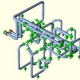
The vibration control and sway brace is shipped ready for installation.
1. Measure the correct space required to install the sway brace assembly. Lay out the sway brace assembly as it is to be installed. Weld one end of structural attachment to the structure and affix the other end with clamp or bolting as required. Make sure the sway brace is located in the same direction as the thermal movement of the pipe. Tighten the adjustment coupling to release the travel stops if supplied. Turn the thrust nut until the bottom of the pressure plate lines up with the pre-load indicated on the nameplate.
2. The brace should be in the proper configuration when it reaches the hot condition. If not, final adjustments can be made by tightening or loosening the adjustment coupling.
i) When properly adjusted, the rod coupling should rotate with slight resistance and the tension test collar can be rotated by hand while holding the rod stationary. There should not be any gap between either end of the pressure and end plates.
ii) Two rod ends should be visible in the adjustment coupling.
When the system shuts down for maintenance, the travel stops should be reinstalled and the same adjustment procedure should be repeated.
i) When properly adjusted, the rod coupling should rotate with slight resistance and the tension test collar can be rotated by hand while holding the rod stationary. There should not be any gap between either end of the pressure and end plates.
ii) Two rod ends should be visible in the adjustment coupling.
When the system shuts down for maintenance, the travel stops should be reinstalled and the same adjustment procedure should be repeated.
In the past few years there has been an increased focus on the so-called ‘hot sustained’ stress in piping system analyses. The ASME B31.3 2006 edition clarified that Sustained stress requirements must be met for all operating conditions of a piping system. There had always been practitioners whose view was that any stress due to change in temperature should be considered secondary. You can still find an interesting discussion on this topic in the CAESAR II manual.
If you read Example 2 in B31.3 Appendix S, you will see that it includes a sustained stress check with the inactive/lifting off support removed. When we try to simulate this by using algebraic load cases, we are essentially taking a short cut to avoid having to run a new model with this support removed. In this post we will see why the use of algebraic load cases in this manner can sometimes be too conservative. It applies more to those of you not using CAESAR II Version 8 or above, but is worth knowing either way. In Version 8, the ‘Alternate-sustained’ case facility was introduced, which produces the same results as creating a separate model.
Lets take a look at the typical load cases used for an algebraic ‘hot sustained’ check:
L1) W+P1+T1+D1 (OPE)
L2) W+P1 (SUS)
L3) T1+D1 (OPE)
L4) L1-L3 (SUS)
L5) L1-L2 (EXP)
L1) W+P1+T1+D1 (OPE)
L2) W+P1 (SUS)
L3) T1+D1 (OPE)
L4) L1-L3 (SUS)
L5) L1-L2 (EXP)
Load case 3 is an artificial construct which represents weightless thermal expansion (plus imposed boundary displacements). Load case 4 is simply the algebraic subtraction of this effect from the operating case – it may be thought of as applying weight to the pipe in the operating configuration.
Where the algebraic case method can differ significantly from the ‘separate model’ approach is when there are multiple single-acting (+Y) restraints. Fortunately there is an easy way to address this issue.
Let me demonstrate by way of an example. Due to thermal expansion of a process column, the connecting piping shown below lifts off at the support nearest to the column (Node 80). This corresponds to case L1. The support at node 90 is nearly ready to lift off but is still resting.
Now consider what happens when we run the artificial load case L3=T1+D1. As the system is completely weightless, every pipe support along the pipe rack will be inactive:
Therefore when we run the algebraic difference case L4, we are considering the imposition of weight starting from a fully floating position. Unsurprisingly, this results in stresses which differ from the traditional hot sustained check (running a separate analysis with the inactive support(s) removed from the model). Even though the span from 90 to 100 and onwards is resting in the operating case, there is a bending moment component to bring the line from the floating position down to the support.
Although the algebraic method is ‘correct’ in that it truly captures the effect of weight in the thermally expanded position, it is in my view overly conservative to consider this as a sustained stress. In a sense, gravity acts like an anchor and can be treated as such; for instance if the pipe had hold-down supports at node 90 and onward the pipe would not float there in the weightless case L3. The algebraic and traditional methods would start to align – yet the hold down supports would not be doing anything in real life. And that, in a nutshell, is how to make the algebraic hot sustained check align with the Code requirement – adding hold-down restraints at supports which do not lift off (change +Y to Y). You wouldn’t need to add hold down supports at every support in the system, but only for sufficient distance from the point of lift-off (usually two or three supports).
Figure 3 shows the weightless thermal case L3 with the addition of hold down restraints at every support except the one that lifts off. Note the similarity to Figure 1, the operating case.
You might object to this method because the hold-down supports aren’t actually there, but the hold-downs simply linearise the analysis and ensure that the assessment is not penalised for supports which do not in fact lift off. Sure, a support may only just be resting and we’re ignoring the portion of stress due to weight transfer away from that support. This aspect is discussed in more detail in the CAESAR II manual, but in my interpretation of the Code it does not matter. The state of physical contact with the support prevents further detrimental effect on the pipe, which is reflective of a secondary stress (self-limiting) rather than primary.
As seen in the table, for this particular model the difference between methods is huge (nb. the sustained stress index has been set to 1.0 x SIF here so it is a little conservative). However, the maximum stress calculated using the algebraic method with hold-downs matches the ‘separate model’ approach. Similarly for the CAESAR II ‘Alternate sustained’ case type. This is a prime example of where an assessment determined using the algebraic hot sustained can be way too conservative.