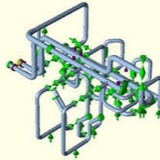
6.3. Exchangers (Shell and Tube)
For piping connected to heat exchangers with T<400°C or P<35 kg/cm2g, the pipe bending stress due to thermal expansion at the exchanger nozzle shall be limited to 700 kg/cm2 using a rigid nozzle analysis. If above criteria is exceeded, localized stress at the nozzle-to-shell be calculated by WRC 107 and WRC 297, and these computed stress value shall be limited in accordance with ASME SECTION VIII.
For piping connected to heat exchangers with T>400°C or P>35 kg/cm2g, the piping imposed loads shall be transmitted to the vendor for his approval.
For piping connected to heat exchangers with T<400°C or P<35 kg/cm2g, the pipe bending stress due to thermal expansion at the exchanger nozzle shall be limited to 700 kg/cm2 using a rigid nozzle analysis. If above criteria is exceeded, localized stress at the nozzle-to-shell be calculated by WRC 107 and WRC 297, and these computed stress value shall be limited in accordance with ASME SECTION VIII.
For piping connected to heat exchangers with T>400°C or P>35 kg/cm2g, the piping imposed loads shall be transmitted to the vendor for his approval.
6.4. Pressure Vessels and Columns
For piping connected to pressure vessels and columns with T<400°C or P<35 kg/cm2g, the pipe bending stress due to thermal expansion at the pressure vessels and columns nozzle shall be limited to 430 kg/cm2 using a rigid nozzle analysis.
If above criteria is exceeded, WRC 107 and WRC 297 shall be used for calculate localized stress at the nozzle-to-shell, and these computed stress value shall be limited in accordance with ASME SECTION VIII.
For piping connected to pressure vessels and columns with T>400°C or P>35 kg/cm2g, the piping imposed loads shall be transmitted to the vendor for his approval.
For piping connected to pressure vessels and columns with T<400°C or P<35 kg/cm2g, the pipe bending stress due to thermal expansion at the pressure vessels and columns nozzle shall be limited to 430 kg/cm2 using a rigid nozzle analysis.
If above criteria is exceeded, WRC 107 and WRC 297 shall be used for calculate localized stress at the nozzle-to-shell, and these computed stress value shall be limited in accordance with ASME SECTION VIII.
For piping connected to pressure vessels and columns with T>400°C or P>35 kg/cm2g, the piping imposed loads shall be transmitted to the vendor for his approval.
6.5. Fired Heaters and Steam Generators
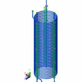
The allowable nozzle loads and moments for fired heater shall be limited to those specified in relevant Engineering specification or API 560 or values that are acceptable to heater vendor.
Displacement of tubes shall be approved by the heater vendor and the effect of expansion and/or displacement of the tubes shall be reflected in the stress analysis of piping system.
Any heater designed with a floating coil (all spring or counter weight mounted) shall be provided with fail-safe limit stops in all directions.
Computer analysis of piping systems connected to floating heater coils shall include the heater coil or an approximate model of the coil as part of systems and the effects of internal guides and restraints. Where heater coils are floating, the support of the connecting piping system shall be completely and independently balanced so that no dead loads imposed on coil.
The allowable nozzle loads and moments for fired heater shall be limited to those specified in relevant Engineering specification or API 560 or values that are acceptable to heater vendor.
Displacement of tubes shall be approved by the heater vendor and the effect of expansion and/or displacement of the tubes shall be reflected in the stress analysis of piping system.
Any heater designed with a floating coil (all spring or counter weight mounted) shall be provided with fail-safe limit stops in all directions.
Computer analysis of piping systems connected to floating heater coils shall include the heater coil or an approximate model of the coil as part of systems and the effects of internal guides and restraints. Where heater coils are floating, the support of the connecting piping system shall be completely and independently balanced so that no dead loads imposed on coil.
6.6. Packaged Equipment
External load limits are to follow the vendor recommendations.
External load limits are to follow the vendor recommendations.
7.0. Piping Restraints
7.1. Pipe supports shall be spaced so as not to cause excessive deflection at any point along the unsupported section of the pipe. As a general guide for piping located in process area, the maximum mid span deflection shall not be allowed to exceed 12 mm and for piping in pipe way, the mid span deflection between straight run of piping shall not be allowed to exceed 12 mm.
7.2. The design, selection, fabrication and installation of piping support shall be in accordance with the “Engineering Specification for Piping Hanging and Support”.
7.3. Piping subjected to two-phase flow and connected to reciprocating compressor shall be supported as rigidly as possible while maintaining acceptability of pipe stresses and equipment nozzle loads.
7.4. For nonmetallic piping, vendor’s recommendation for flexibility analysis, support spacing and support type shall be utilized.
7.1. Pipe supports shall be spaced so as not to cause excessive deflection at any point along the unsupported section of the pipe. As a general guide for piping located in process area, the maximum mid span deflection shall not be allowed to exceed 12 mm and for piping in pipe way, the mid span deflection between straight run of piping shall not be allowed to exceed 12 mm.
7.2. The design, selection, fabrication and installation of piping support shall be in accordance with the “Engineering Specification for Piping Hanging and Support”.
7.3. Piping subjected to two-phase flow and connected to reciprocating compressor shall be supported as rigidly as possible while maintaining acceptability of pipe stresses and equipment nozzle loads.
7.4. For nonmetallic piping, vendor’s recommendation for flexibility analysis, support spacing and support type shall be utilized.
8.0. Miscellaneous
8.1. Reports
Final calculation of the grade “C” and the grade “B” which are analyzed by formal computer analysis will be submitted to owner for record and site modification of piping. The piping systems which are classified as grade “B” shall be analyzed by formal computer analysis if experienced stress engineers decide it necessary to prove that the systems meet the allowance of this specification. The reports shall comprise of the following:
❗️Basic data and calculated conditions
❗️Layout isometric and support type and location
❗️Load cases and calculated member stresses
❗️Forces, moments and displacement reports
❗️Spring hanger and expansion joint design parameters
8.1. Reports
Final calculation of the grade “C” and the grade “B” which are analyzed by formal computer analysis will be submitted to owner for record and site modification of piping. The piping systems which are classified as grade “B” shall be analyzed by formal computer analysis if experienced stress engineers decide it necessary to prove that the systems meet the allowance of this specification. The reports shall comprise of the following:
❗️Basic data and calculated conditions
❗️Layout isometric and support type and location
❗️Load cases and calculated member stresses
❗️Forces, moments and displacement reports
❗️Spring hanger and expansion joint design parameters
8.2. Units
Metric units (kg, mm, kg-m, kg/cm2) shall be used as a unit of control for analysis.
Metric units (kg, mm, kg-m, kg/cm2) shall be used as a unit of control for analysis.
8.3. Softwares
CAESAR II Ver x.xx (produced by COADE Inc.) will be used for formal computer analysis.
CAESAR II Ver x.xx (produced by COADE Inc.) will be used for formal computer analysis.
This media is not supported in your browser
VIEW IN TELEGRAM
Expansion loop
1_4899975514803929282.pdf
1.6 MB
PSV Calculation and Philosophy
The vibration control and sway brace is shipped ready for installation.
1. Measure the correct space required to install the sway brace assembly. Lay out the sway brace assembly as it is to be installed. Weld one end of structural attachment to the structure and affix the other end with clamp or bolting as required. Make sure the sway brace is located in the same direction as the thermal movement of the pipe. Tighten the adjustment coupling to release the travel stops if supplied. Turn the thrust nut until the bottom of the pressure plate lines up with the pre-load indicated on the nameplate.
2. The brace should be in the proper configuration when it reaches the hot condition. If not, final adjustments can be made by tightening or loosening the adjustment coupling.
i) When properly adjusted, the rod coupling should rotate with slight resistance and the tension test collar can be rotated by hand while holding the rod stationary. There should not be any gap between either end of the pressure and end plates.
ii) Two rod ends should be visible in the adjustment coupling.
When the system shuts down for maintenance, the travel stops should be reinstalled and the same adjustment procedure should be repeated.
i) When properly adjusted, the rod coupling should rotate with slight resistance and the tension test collar can be rotated by hand while holding the rod stationary. There should not be any gap between either end of the pressure and end plates.
ii) Two rod ends should be visible in the adjustment coupling.
When the system shuts down for maintenance, the travel stops should be reinstalled and the same adjustment procedure should be repeated.
In the past few years there has been an increased focus on the so-called ‘hot sustained’ stress in piping system analyses. The ASME B31.3 2006 edition clarified that Sustained stress requirements must be met for all operating conditions of a piping system. There had always been practitioners whose view was that any stress due to change in temperature should be considered secondary. You can still find an interesting discussion on this topic in the CAESAR II manual.