Forwarded from ️Oil And Gas️ (Ehsan Salimi)
This media is not supported in your browser
VIEW IN TELEGRAM
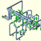
Water hammer arrestors are used to absorb the shock when water flowing in a
piping system suddenly stops due to fast closing shutoff valves,
dishwashers, and clothes washers. This action protects against annoying and
potentially damaging effects of water hammer.
piping system suddenly stops due to fast closing shutoff valves,
dishwashers, and clothes washers. This action protects against annoying and
potentially damaging effects of water hammer.
Forwarded from Sirus Yahyapour
Stress on Tee Conection.pdf
589.4 KB
Forwarded from Piping Stress Analysis (PSA Group)
External Nozzle Loads Design Using WRC-107/537
BASICS OF PIPING STRESS ANALYSIS ⬇️⬇️⬇️
Pipes are the most delicate components in any process plant, they are also the busiest entities. Piping Systems are subjected to almost all kinds of loads, intentional or unintentional. It is very important to take note of all potential loads that a piping system would encounter during operation as well as during other stages in the life cycle of a process plant. Ignoring any such load while designing, erecting, hydro-testing, start-up shut-down, normal operation, maintenance etc. can lead to inadequate design of a piping system. The system may fail on the first occurrence of this overlooked load. Failure of a piping system may trigger a Domino effect and cause a major disaster.
As the pipe temperature changes from the installation condition to the operating condition, it expands or contracts. In the general term, both cases are called thermal expansion. When a pipe expands it has the potential of generating enormous force and stress in the system. However, if the piping is flexible enough, the expansion can be absorbed without creating undue force or stress. Providing the proper flexibility is one of the major tasks in the design of piping systems.
Piping is used to convey a certain amount of fluid from one point to another. It is obvious that the shorter the pipe is used the lesser the capital expenditure is required. Long pipe runs may also generate excessive pressure drop making it unsuitable for the proper operation. However, the direct shortest layout generally is not acceptable for absorbing the thermal expansion. Flexibility analysis is done on the piping system to study its behaviour when its temperature changes from ambient to operating, so as to arrive to the most economical layout with adequate safety. Piping flexibility is provided in many different ways.
Pipes bend, even under their own weight. The longer the pipe, the easier it is to bend. If a pipe is bent within its elastic limit (no permanent deformation), it will behave like a spring and return to its original shape after the load is removed. If the elbows and anchors on a pipe system are arranged to allow movement, the forces will be much less than a straight run. Also, the turns and offsets needed for running the pipe from one point to another provides some flexibility as well. This inherent flexibility may or may not be sufficient depending on the individual cases.
✏️Piping Stress Analysis Engineering Specification
This content provides you with sample piping stress analysis Engineering Specification that is used in industrial plant construction works.
This content provides you with sample piping stress analysis Engineering Specification that is used in industrial plant construction works.
1. Piping Stress Analysis - Scope
This specification prescribes the basic requirements for stress analysis of the piping systems to be performed during the piping design work for use in industrial plant.
This specification prescribes the basic requirements for stress analysis of the piping systems to be performed during the piping design work for use in industrial plant.
2. References
The latest edition / version of the following codes, standards and specifications shall form a part of the requirements of this specifications.
2.1. Piping Stress Analysis - Codes and Standards
⬇️ASME B31.3
Process Piping
⬇️ASME section VIII div 1
Boiler and Pressure Vessel Code
⬇️ASME section VIII div 2
Rule for Construction of Pressure Vessels
⬇️API 610
Centrifugal pumps for petroleum, heavy duty chemical, and gas industry services
⬇️API 617
Centrifugal compressors for petroleum, chemical, and gas service industries
⬇️API 618
Reciprocating compressors for petroleum, chemical, and gas service industries
⬇️API 560
Fired heaters for general refinery services
⬇️API 650
Welded steel tanks for oil storage
⬇️API 660
Shell and tube type heat exchangers for general refinery services
⬇️API 661
Air-Cooled heat exchangers for general refinery services
⬇️API RP520
Sizing, selection and installation of pressure – relieving device in refineries
⬇️NEMA SM23
Steam turbine for mechanical drive service
⬇️EJMA
Standard of expansion joint manufacturers association – ASME 16.9, ASME 16.25
⬇️WRC 107
Local stresses in spherical and cylindrical shells due to external loading
⬇️WRC 297
Supplement for WRC 107
The latest edition / version of the following codes, standards and specifications shall form a part of the requirements of this specifications.
2.1. Piping Stress Analysis - Codes and Standards
⬇️ASME B31.3
Process Piping
⬇️ASME section VIII div 1
Boiler and Pressure Vessel Code
⬇️ASME section VIII div 2
Rule for Construction of Pressure Vessels
⬇️API 610
Centrifugal pumps for petroleum, heavy duty chemical, and gas industry services
⬇️API 617
Centrifugal compressors for petroleum, chemical, and gas service industries
⬇️API 618
Reciprocating compressors for petroleum, chemical, and gas service industries
⬇️API 560
Fired heaters for general refinery services
⬇️API 650
Welded steel tanks for oil storage
⬇️API 660
Shell and tube type heat exchangers for general refinery services
⬇️API 661
Air-Cooled heat exchangers for general refinery services
⬇️API RP520
Sizing, selection and installation of pressure – relieving device in refineries
⬇️NEMA SM23
Steam turbine for mechanical drive service
⬇️EJMA
Standard of expansion joint manufacturers association – ASME 16.9, ASME 16.25
⬇️WRC 107
Local stresses in spherical and cylindrical shells due to external loading
⬇️WRC 297
Supplement for WRC 107
2.2. Piping Stress Analysis - Related Specifications and References
⬇️Engineering specification for Piping Hanging & Support
⬇️Engineering specification for Piping Design
⬇️Engineering specification for Thermal Insulation (HOT)
⬇️Engineering specification for Thermal Insulation (COLD)
⬇️Engineering specification for Piping Material
⬇️Engineering specification for Piping Hanging & Support
⬇️Engineering specification for Piping Design
⬇️Engineering specification for Thermal Insulation (HOT)
⬇️Engineering specification for Thermal Insulation (COLD)
⬇️Engineering specification for Piping Material
3. Piping Stress Analysis -Design Conditions
The piping stress analysis shall include the following loading effects as applicable.
The piping stress analysis shall include the following loading effects as applicable.
3.1. Piping Stress Analysis - Weight Effects
The weight load shall include the pipe weight, weight of content, insulation weight and weight of fittings and any inline equipment. For piping systems, which are tested hydraulically and have content with specific gravity less than 1.0, a hydro-test run shall be performed assuming a specific gravity of 1.0 to establish the structural design loads.
The weight load shall include the pipe weight, weight of content, insulation weight and weight of fittings and any inline equipment. For piping systems, which are tested hydraulically and have content with specific gravity less than 1.0, a hydro-test run shall be performed assuming a specific gravity of 1.0 to establish the structural design loads.
3.2. Piping Stress Analysis - Thermal Effects
Temperature to be used in the piping flexibility analysis shall be the maximum differential temperature between any of the following applicable conditions.
3.2.1. Piping Stress Analysis - Installation Temperature
1) Maximum dry bulb temperature of 48°C shall be taken as the installation temperature for cold insulated piping service.
2) Minimum dry bulb temperature of 5°C shall be taken as the installation temperature for bare/hot insulated piping service.
3.2.2. Piping Stress Analysis - Calculation Temperature
1) Operating temperature as stipulated in the line list.
2) In addition, the following temperature condition shall be considered in the calculation when lines are specified in the line index.
⬇️ Start-up / shutdown temperature
⬇️Steam out temperature: Normal steam out temperature should not exceed 120°C for saturated steam. This steam out temperature shall be considered only for flexibility purposes of hydrocarbon serviced lines.
⬇️Decoking temperature
⬇️Regeneration temperature
3) For piping which normally have no flow (such as drains, start-up lines, etc.) the flow calculation temperature shall be determined as follows.
For insulated piping, 75% of operating temperature shall be taken.
For un-insulated piping, 25% of operating temperature shall be taken.
For section between stand-by equipment and cut-off valve, installation temperature shall be taken.
For piping which have warming-up by-pass, operating temperature shall be taken for all section.
Temperature to be used in the piping flexibility analysis shall be the maximum differential temperature between any of the following applicable conditions.
3.2.1. Piping Stress Analysis - Installation Temperature
1) Maximum dry bulb temperature of 48°C shall be taken as the installation temperature for cold insulated piping service.
2) Minimum dry bulb temperature of 5°C shall be taken as the installation temperature for bare/hot insulated piping service.
3.2.2. Piping Stress Analysis - Calculation Temperature
1) Operating temperature as stipulated in the line list.
2) In addition, the following temperature condition shall be considered in the calculation when lines are specified in the line index.
⬇️ Start-up / shutdown temperature
⬇️Steam out temperature: Normal steam out temperature should not exceed 120°C for saturated steam. This steam out temperature shall be considered only for flexibility purposes of hydrocarbon serviced lines.
⬇️Decoking temperature
⬇️Regeneration temperature
3) For piping which normally have no flow (such as drains, start-up lines, etc.) the flow calculation temperature shall be determined as follows.
For insulated piping, 75% of operating temperature shall be taken.
For un-insulated piping, 25% of operating temperature shall be taken.
For section between stand-by equipment and cut-off valve, installation temperature shall be taken.
For piping which have warming-up by-pass, operating temperature shall be taken for all section.
3.3. Piping Stress Analysis - Pressure Effect
Maximum operating pressure and minimum vacuum pressure shall be taken as the calculation pressure as per ASME B31.3, unless otherwise specified.
Maximum operating pressure and minimum vacuum pressure shall be taken as the calculation pressure as per ASME B31.3, unless otherwise specified.
3.4. Piping Stress Analysis - Friction Effects
3.4.1 Friction effects shall be considered in the design of anchor on horizontally long run piping system with OD larger than 8 inch.
3.4.2 Following friction factor shall be used for computing the frictional resistance.
Surface Friction Factor
Steel to Steel = 0.3
Steel to Teflon = 0.1
Teflon to Teflon = 0.06
Steel to Concrete = 0.5
3.4.1 Friction effects shall be considered in the design of anchor on horizontally long run piping system with OD larger than 8 inch.
3.4.2 Following friction factor shall be used for computing the frictional resistance.
Surface Friction Factor
Steel to Steel = 0.3
Steel to Teflon = 0.1
Teflon to Teflon = 0.06
Steel to Concrete = 0.5
3.5. Piping Stress Analysis - Wind and Earthquake Effects
3.5.1. Wind and earthquake effects shall be checked in formal computer analysis, if experienced stress engineers decide it necessary. Wind loading shall be considered for sizes 24NB and over, for heights more than 10 m above grade where not shielded. For earthquake loading the equivalent static force analysis method shall be applied. The wind load and Earthquake as acting separately in two lateral condition 90º apart. 2.
3.5.1. Wind and earthquake effects shall be checked in formal computer analysis, if experienced stress engineers decide it necessary. Wind loading shall be considered for sizes 24NB and over, for heights more than 10 m above grade where not shielded. For earthquake loading the equivalent static force analysis method shall be applied. The wind load and Earthquake as acting separately in two lateral condition 90º apart. 2.
4.0 Piping Stress Analysis - Design and Analysis Requirements for Flexibility
4.1. Piping to purged vessels that cannot be disconnected during purging shall be designed with sufficient flexibility to accommodate the thermal displacement of the vessel.
4.2. The use of cold spring in piping, which connects to rotating equipment, is prohibited.
4.3. If temperature, resulting in short term loading as those stated in Para. 3.2.2.2) is specified in the line list, thermal effect by this temperature shall also be considered in the analysis. However, the reaction loads at equipment shall not be taken from this alternate analysis case.
4.1. Piping to purged vessels that cannot be disconnected during purging shall be designed with sufficient flexibility to accommodate the thermal displacement of the vessel.
4.2. The use of cold spring in piping, which connects to rotating equipment, is prohibited.
4.3. If temperature, resulting in short term loading as those stated in Para. 3.2.2.2) is specified in the line list, thermal effect by this temperature shall also be considered in the analysis. However, the reaction loads at equipment shall not be taken from this alternate analysis case.