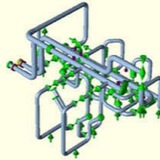
The vibration control and sway brace is shipped ready for installation.
1. Measure the correct space required to install the sway brace assembly. Lay out the sway brace assembly as it is to be installed. Weld one end of structural attachment to the structure and affix the other end with clamp or bolting as required. Make sure the sway brace is located in the same direction as the thermal movement of the pipe. Tighten the adjustment coupling to release the travel stops if supplied. Turn the thrust nut until the bottom of the pressure plate lines up with the pre-load indicated on the nameplate.
2. The brace should be in the proper configuration when it reaches the hot condition. If not, final adjustments can be made by tightening or loosening the adjustment coupling.
i) When properly adjusted, the rod coupling should rotate with slight resistance and the tension test collar can be rotated by hand while holding the rod stationary. There should not be any gap between either end of the pressure and end plates.
ii) Two rod ends should be visible in the adjustment coupling.
When the system shuts down for maintenance, the travel stops should be reinstalled and the same adjustment procedure should be repeated.
1. Measure the correct space required to install the sway brace assembly. Lay out the sway brace assembly as it is to be installed. Weld one end of structural attachment to the structure and affix the other end with clamp or bolting as required. Make sure the sway brace is located in the same direction as the thermal movement of the pipe. Tighten the adjustment coupling to release the travel stops if supplied. Turn the thrust nut until the bottom of the pressure plate lines up with the pre-load indicated on the nameplate.
2. The brace should be in the proper configuration when it reaches the hot condition. If not, final adjustments can be made by tightening or loosening the adjustment coupling.
i) When properly adjusted, the rod coupling should rotate with slight resistance and the tension test collar can be rotated by hand while holding the rod stationary. There should not be any gap between either end of the pressure and end plates.
ii) Two rod ends should be visible in the adjustment coupling.
When the system shuts down for maintenance, the travel stops should be reinstalled and the same adjustment procedure should be repeated.
WHAT DOES THE HOT OR COLD SETTING MEAN ON A CONSTANT SPRING SUPPORT?
The “cold” setting on a constant spring support refers to the location of the pipe at the installed position. The “hot” setting refers to the design location of the pipe at the operating position. In general, prior to installation, all spring supports are set at the “cold” setting.
The “cold” setting on a constant spring support refers to the location of the pipe at the installed position. The “hot” setting refers to the design location of the pipe at the operating position. In general, prior to installation, all spring supports are set at the “cold” setting.
animation.gif
39.7 KB
Pipework and/or vessels subject to temperature change or subsidence, etc. which give rise to vertical displacements should be supported by a resilient device which will absorb/accommodate the movement. For relatively small displacements (up to about 75mm) the variable spring support is recommended.
Standard ranges of variable spring supports are produced in four basic travel ranges; 35mm, 70mm, 140mm and 210mm. The travels stated are the maximum working range of the springs. This full travel can be used providing the necessary calculations are carried out to ensure that the connecting equipment and pipework can withstand the large load changes that occur during pipe movement.
Most national standards do limit the load variation to maximum of 25%. It is therefore usual to select variable spring supports on this basis.
Standard ranges of variable spring supports are produced in four basic travel ranges; 35mm, 70mm, 140mm and 210mm. The travels stated are the maximum working range of the springs. This full travel can be used providing the necessary calculations are carried out to ensure that the connecting equipment and pipework can withstand the large load changes that occur during pipe movement.
Most national standards do limit the load variation to maximum of 25%. It is therefore usual to select variable spring supports on this basis.
Load setting and blocking ⬇️⬇️⬇️
Spring hangers and supports are preset at the works to the installation load and blocked in both directions of movement. Blocking is necessary to take up additional loads during pickling, flushing, or hydrostatic tests. The factory settings are carried out on electronically controlled test benches:
* with spring hangers, values set at the factory are stamped onto a riveted name plate.
* the installation position is marked on the travel scale.
* cold and hot settings are marked on the travel scale with a white and red sticker respectively
* the blocking device can be blocked in any position
* The blocking pieces can be reinserted in any required position
Spring hangers and supports should be set in such a way that the spring load and the piping weight correspond with the cold load position. The corresponding hot load position results from the theoretically determined pipe movement (travel) and the spring rate. The load difference between the cold and hot positions acts on the piping as a reaction force and is limited by the relevant design specifications. Generally, the max. permissible load deviation amounts to 25% of the operating load.
Spring hangers and supports are preset at the works to the installation load and blocked in both directions of movement. Blocking is necessary to take up additional loads during pickling, flushing, or hydrostatic tests. The factory settings are carried out on electronically controlled test benches:
* with spring hangers, values set at the factory are stamped onto a riveted name plate.
* the installation position is marked on the travel scale.
* cold and hot settings are marked on the travel scale with a white and red sticker respectively
* the blocking device can be blocked in any position
* The blocking pieces can be reinserted in any required position
Spring hangers and supports should be set in such a way that the spring load and the piping weight correspond with the cold load position. The corresponding hot load position results from the theoretically determined pipe movement (travel) and the spring rate. The load difference between the cold and hot positions acts on the piping as a reaction force and is limited by the relevant design specifications. Generally, the max. permissible load deviation amounts to 25% of the operating load.
Forwarded from ️Oil And Gas️ (Ehsan Salimi)
This media is not supported in your browser
VIEW IN TELEGRAM
Water hammer arrestors are used to absorb the shock when water flowing in a
piping system suddenly stops due to fast closing shutoff valves,
dishwashers, and clothes washers. This action protects against annoying and
potentially damaging effects of water hammer.
piping system suddenly stops due to fast closing shutoff valves,
dishwashers, and clothes washers. This action protects against annoying and
potentially damaging effects of water hammer.
Forwarded from Sirus Yahyapour
Stress on Tee Conection.pdf
589.4 KB
Forwarded from Piping Stress Analysis (PSA Group)
External Nozzle Loads Design Using WRC-107/537
BASICS OF PIPING STRESS ANALYSIS ⬇️⬇️⬇️
Pipes are the most delicate components in any process plant, they are also the busiest entities. Piping Systems are subjected to almost all kinds of loads, intentional or unintentional. It is very important to take note of all potential loads that a piping system would encounter during operation as well as during other stages in the life cycle of a process plant. Ignoring any such load while designing, erecting, hydro-testing, start-up shut-down, normal operation, maintenance etc. can lead to inadequate design of a piping system. The system may fail on the first occurrence of this overlooked load. Failure of a piping system may trigger a Domino effect and cause a major disaster.
As the pipe temperature changes from the installation condition to the operating condition, it expands or contracts. In the general term, both cases are called thermal expansion. When a pipe expands it has the potential of generating enormous force and stress in the system. However, if the piping is flexible enough, the expansion can be absorbed without creating undue force or stress. Providing the proper flexibility is one of the major tasks in the design of piping systems.
Piping is used to convey a certain amount of fluid from one point to another. It is obvious that the shorter the pipe is used the lesser the capital expenditure is required. Long pipe runs may also generate excessive pressure drop making it unsuitable for the proper operation. However, the direct shortest layout generally is not acceptable for absorbing the thermal expansion. Flexibility analysis is done on the piping system to study its behaviour when its temperature changes from ambient to operating, so as to arrive to the most economical layout with adequate safety. Piping flexibility is provided in many different ways.
Pipes bend, even under their own weight. The longer the pipe, the easier it is to bend. If a pipe is bent within its elastic limit (no permanent deformation), it will behave like a spring and return to its original shape after the load is removed. If the elbows and anchors on a pipe system are arranged to allow movement, the forces will be much less than a straight run. Also, the turns and offsets needed for running the pipe from one point to another provides some flexibility as well. This inherent flexibility may or may not be sufficient depending on the individual cases.
✏️Piping Stress Analysis Engineering Specification
This content provides you with sample piping stress analysis Engineering Specification that is used in industrial plant construction works.
This content provides you with sample piping stress analysis Engineering Specification that is used in industrial plant construction works.
1. Piping Stress Analysis - Scope
This specification prescribes the basic requirements for stress analysis of the piping systems to be performed during the piping design work for use in industrial plant.
This specification prescribes the basic requirements for stress analysis of the piping systems to be performed during the piping design work for use in industrial plant.
2. References
The latest edition / version of the following codes, standards and specifications shall form a part of the requirements of this specifications.
2.1. Piping Stress Analysis - Codes and Standards
⬇️ASME B31.3
Process Piping
⬇️ASME section VIII div 1
Boiler and Pressure Vessel Code
⬇️ASME section VIII div 2
Rule for Construction of Pressure Vessels
⬇️API 610
Centrifugal pumps for petroleum, heavy duty chemical, and gas industry services
⬇️API 617
Centrifugal compressors for petroleum, chemical, and gas service industries
⬇️API 618
Reciprocating compressors for petroleum, chemical, and gas service industries
⬇️API 560
Fired heaters for general refinery services
⬇️API 650
Welded steel tanks for oil storage
⬇️API 660
Shell and tube type heat exchangers for general refinery services
⬇️API 661
Air-Cooled heat exchangers for general refinery services
⬇️API RP520
Sizing, selection and installation of pressure – relieving device in refineries
⬇️NEMA SM23
Steam turbine for mechanical drive service
⬇️EJMA
Standard of expansion joint manufacturers association – ASME 16.9, ASME 16.25
⬇️WRC 107
Local stresses in spherical and cylindrical shells due to external loading
⬇️WRC 297
Supplement for WRC 107
The latest edition / version of the following codes, standards and specifications shall form a part of the requirements of this specifications.
2.1. Piping Stress Analysis - Codes and Standards
⬇️ASME B31.3
Process Piping
⬇️ASME section VIII div 1
Boiler and Pressure Vessel Code
⬇️ASME section VIII div 2
Rule for Construction of Pressure Vessels
⬇️API 610
Centrifugal pumps for petroleum, heavy duty chemical, and gas industry services
⬇️API 617
Centrifugal compressors for petroleum, chemical, and gas service industries
⬇️API 618
Reciprocating compressors for petroleum, chemical, and gas service industries
⬇️API 560
Fired heaters for general refinery services
⬇️API 650
Welded steel tanks for oil storage
⬇️API 660
Shell and tube type heat exchangers for general refinery services
⬇️API 661
Air-Cooled heat exchangers for general refinery services
⬇️API RP520
Sizing, selection and installation of pressure – relieving device in refineries
⬇️NEMA SM23
Steam turbine for mechanical drive service
⬇️EJMA
Standard of expansion joint manufacturers association – ASME 16.9, ASME 16.25
⬇️WRC 107
Local stresses in spherical and cylindrical shells due to external loading
⬇️WRC 297
Supplement for WRC 107
2.2. Piping Stress Analysis - Related Specifications and References
⬇️Engineering specification for Piping Hanging & Support
⬇️Engineering specification for Piping Design
⬇️Engineering specification for Thermal Insulation (HOT)
⬇️Engineering specification for Thermal Insulation (COLD)
⬇️Engineering specification for Piping Material
⬇️Engineering specification for Piping Hanging & Support
⬇️Engineering specification for Piping Design
⬇️Engineering specification for Thermal Insulation (HOT)
⬇️Engineering specification for Thermal Insulation (COLD)
⬇️Engineering specification for Piping Material