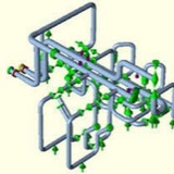
The stress is caused by the pipe pushing against some fixed restraint. Thermal stresses are “secondary stresses” because they are self-limiting. That is, yielding or deformation of the part reduces the stress.
Higher stresses are allowed than in the primary case because of this self limiting behavior. Stresses above the yield point can be acceptable, however, over time, an accumulation of highly stressed thermal cycles can exceed the fatigue capacity of the material leading to failure.
Higher stresses are allowed than in the primary case because of this self limiting behavior. Stresses above the yield point can be acceptable, however, over time, an accumulation of highly stressed thermal cycles can exceed the fatigue capacity of the material leading to failure.
Occasional Stress ⬇️⬇️⬇️
Wind and seismic loads are occasional. In this example sideways seismic loads create the stress.
Wind and seismic loads are occasional. In this example sideways seismic loads create the stress.
The supports for a loop like this would have to be carefully considered to maintain the flexibility while also providing the required support for seismic loads.
Loads like those induced by seismic events are not expected to occur frequently, so the generated stresses are allowed to be higher than primary loads. Seismic stresses are typically allowed to be 20% higher than primary stresses in ASME piping codes. The equipment should be able to survive these rarely occurring stresses without damage.
The vibration control and sway brace is shipped ready for installation.
1. Measure the correct space required to install the sway brace assembly. Lay out the sway brace assembly as it is to be installed. Weld one end of structural attachment to the structure and affix the other end with clamp or bolting as required. Make sure the sway brace is located in the same direction as the thermal movement of the pipe. Tighten the adjustment coupling to release the travel stops if supplied. Turn the thrust nut until the bottom of the pressure plate lines up with the pre-load indicated on the nameplate.
2. The brace should be in the proper configuration when it reaches the hot condition. If not, final adjustments can be made by tightening or loosening the adjustment coupling.
i) When properly adjusted, the rod coupling should rotate with slight resistance and the tension test collar can be rotated by hand while holding the rod stationary. There should not be any gap between either end of the pressure and end plates.
ii) Two rod ends should be visible in the adjustment coupling.
When the system shuts down for maintenance, the travel stops should be reinstalled and the same adjustment procedure should be repeated.
1. Measure the correct space required to install the sway brace assembly. Lay out the sway brace assembly as it is to be installed. Weld one end of structural attachment to the structure and affix the other end with clamp or bolting as required. Make sure the sway brace is located in the same direction as the thermal movement of the pipe. Tighten the adjustment coupling to release the travel stops if supplied. Turn the thrust nut until the bottom of the pressure plate lines up with the pre-load indicated on the nameplate.
2. The brace should be in the proper configuration when it reaches the hot condition. If not, final adjustments can be made by tightening or loosening the adjustment coupling.
i) When properly adjusted, the rod coupling should rotate with slight resistance and the tension test collar can be rotated by hand while holding the rod stationary. There should not be any gap between either end of the pressure and end plates.
ii) Two rod ends should be visible in the adjustment coupling.
When the system shuts down for maintenance, the travel stops should be reinstalled and the same adjustment procedure should be repeated.
WHAT DOES THE HOT OR COLD SETTING MEAN ON A CONSTANT SPRING SUPPORT?
The “cold” setting on a constant spring support refers to the location of the pipe at the installed position. The “hot” setting refers to the design location of the pipe at the operating position. In general, prior to installation, all spring supports are set at the “cold” setting.
The “cold” setting on a constant spring support refers to the location of the pipe at the installed position. The “hot” setting refers to the design location of the pipe at the operating position. In general, prior to installation, all spring supports are set at the “cold” setting.
animation.gif
39.7 KB
Pipework and/or vessels subject to temperature change or subsidence, etc. which give rise to vertical displacements should be supported by a resilient device which will absorb/accommodate the movement. For relatively small displacements (up to about 75mm) the variable spring support is recommended.
Standard ranges of variable spring supports are produced in four basic travel ranges; 35mm, 70mm, 140mm and 210mm. The travels stated are the maximum working range of the springs. This full travel can be used providing the necessary calculations are carried out to ensure that the connecting equipment and pipework can withstand the large load changes that occur during pipe movement.
Most national standards do limit the load variation to maximum of 25%. It is therefore usual to select variable spring supports on this basis.
Standard ranges of variable spring supports are produced in four basic travel ranges; 35mm, 70mm, 140mm and 210mm. The travels stated are the maximum working range of the springs. This full travel can be used providing the necessary calculations are carried out to ensure that the connecting equipment and pipework can withstand the large load changes that occur during pipe movement.
Most national standards do limit the load variation to maximum of 25%. It is therefore usual to select variable spring supports on this basis.
Load setting and blocking ⬇️⬇️⬇️
Spring hangers and supports are preset at the works to the installation load and blocked in both directions of movement. Blocking is necessary to take up additional loads during pickling, flushing, or hydrostatic tests. The factory settings are carried out on electronically controlled test benches:
* with spring hangers, values set at the factory are stamped onto a riveted name plate.
* the installation position is marked on the travel scale.
* cold and hot settings are marked on the travel scale with a white and red sticker respectively
* the blocking device can be blocked in any position
* The blocking pieces can be reinserted in any required position
Spring hangers and supports should be set in such a way that the spring load and the piping weight correspond with the cold load position. The corresponding hot load position results from the theoretically determined pipe movement (travel) and the spring rate. The load difference between the cold and hot positions acts on the piping as a reaction force and is limited by the relevant design specifications. Generally, the max. permissible load deviation amounts to 25% of the operating load.
Spring hangers and supports are preset at the works to the installation load and blocked in both directions of movement. Blocking is necessary to take up additional loads during pickling, flushing, or hydrostatic tests. The factory settings are carried out on electronically controlled test benches:
* with spring hangers, values set at the factory are stamped onto a riveted name plate.
* the installation position is marked on the travel scale.
* cold and hot settings are marked on the travel scale with a white and red sticker respectively
* the blocking device can be blocked in any position
* The blocking pieces can be reinserted in any required position
Spring hangers and supports should be set in such a way that the spring load and the piping weight correspond with the cold load position. The corresponding hot load position results from the theoretically determined pipe movement (travel) and the spring rate. The load difference between the cold and hot positions acts on the piping as a reaction force and is limited by the relevant design specifications. Generally, the max. permissible load deviation amounts to 25% of the operating load.
Forwarded from ️Oil And Gas️ (Ehsan Salimi)
This media is not supported in your browser
VIEW IN TELEGRAM
Water hammer arrestors are used to absorb the shock when water flowing in a
piping system suddenly stops due to fast closing shutoff valves,
dishwashers, and clothes washers. This action protects against annoying and
potentially damaging effects of water hammer.
piping system suddenly stops due to fast closing shutoff valves,
dishwashers, and clothes washers. This action protects against annoying and
potentially damaging effects of water hammer.
Forwarded from Sirus Yahyapour
Stress on Tee Conection.pdf
589.4 KB
Forwarded from Piping Stress Analysis (PSA Group)
External Nozzle Loads Design Using WRC-107/537
BASICS OF PIPING STRESS ANALYSIS ⬇️⬇️⬇️