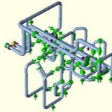
LOOP-1
An unbalanced expansion loop. Normally a pipe loop is located midspan between anchors providing uniform displacement on each side minimizing the size of the loop. In this case an unbalanced loop is chosen to reduce the loads on the vessel nozzle by placing an axial anchor that limits axial motion next to it. The trade-off is the increase in height required for the loop. The anchor and pipe loop location is a trade-off.
An unbalanced expansion loop. Normally a pipe loop is located midspan between anchors providing uniform displacement on each side minimizing the size of the loop. In this case an unbalanced loop is chosen to reduce the loads on the vessel nozzle by placing an axial anchor that limits axial motion next to it. The trade-off is the increase in height required for the loop. The anchor and pipe loop location is a trade-off.
A tower with a guided flexible pipe connection. The guided connection allows the flexibility required in the nozzle while limiting the loads applied to the vessel nozzle. Modelling the flexibility of the nozzle and accounting for the different possible temperatures of the piping system and tower is required for successful analysis.
Pump
Stress analysis of a pump skid from storage towers to dual pumps. The temperature distribution of the piping varies depending on which pump or pumps are running. Here the pipes leading to the operating pump are hotter than the standby pipes. Multiple load cases are required to ensure the piping design is acceptable.
Stress analysis of a pump skid from storage towers to dual pumps. The temperature distribution of the piping varies depending on which pump or pumps are running. Here the pipes leading to the operating pump are hotter than the standby pipes. Multiple load cases are required to ensure the piping design is acceptable.
Types of Stresses in Piping Systems ⬇️
Primary, Secondary and Occasional Loads
From a piping stress analysis point of view the following are the main loads to be considered for the design:
Primary, Secondary and Occasional Loads
From a piping stress analysis point of view the following are the main loads to be considered for the design:
⬇️ Primary load occurs from Sustained loads like dead weight, live weight, internal pressure etc. and are called non-self-limiting loads. Pressure thrust from an expansion joint is used in this article.
⬇️⬇️ Secondary loads occur from thermal expansion loads like temperature change, anchors and restraints etc. and are called self-limiting loads. Thermal expansion in a horizontal pipe loop is used in this article.
⬇️⬇️⬇️ Occasional loads occur from static wind and seismic loads and are considered to act occasionally. Seismic load on a vertical pipe loop is used in this article.
⬇️⬇️ Secondary loads occur from thermal expansion loads like temperature change, anchors and restraints etc. and are called self-limiting loads. Thermal expansion in a horizontal pipe loop is used in this article.
⬇️⬇️⬇️ Occasional loads occur from static wind and seismic loads and are considered to act occasionally. Seismic load on a vertical pipe loop is used in this article.
Primary Stress ⬇️
Primary Stress is generated by internal and external force and moments. Primary stress is not self limiting – even if a part moves, the load causing it does not reduce. In this example, an expansion joint without restraining hardware creates a primary stress on a pipe.
Primary Stress is generated by internal and external force and moments. Primary stress is not self limiting – even if a part moves, the load causing it does not reduce. In this example, an expansion joint without restraining hardware creates a primary stress on a pipe.
Expansion-joint-stress
Pipe stress as reported by Caesar. The untied joint is applying a bending force, which, depending on the stress level, Caesar can report as a fail. This design does not meet the expansion joint manufacturers requirements for guiding and anchoring. The pipe with the tied joint is okay.
Pipe stress as reported by Caesar. The untied joint is applying a bending force, which, depending on the stress level, Caesar can report as a fail. This design does not meet the expansion joint manufacturers requirements for guiding and anchoring. The pipe with the tied joint is okay.
This primary stress is caused by pressure of the fluid multiplied by the area of the pipe. It occurs all the time the system is pressurized. No matter how much the pipe displaces, the untied bellows keeps pushing on it.
Because primary stresses are not relieved by the piping moving or yielding, primary stress limits are set lower than other allowable stresses. For example, if primary stresses managed to get above the yield point, the piping would balloon out and explode. The piping codes keep the primary stresses below the yield point by a factor of safety.
Because primary stresses are not relieved by the piping moving or yielding, primary stress limits are set lower than other allowable stresses. For example, if primary stresses managed to get above the yield point, the piping would balloon out and explode. The piping codes keep the primary stresses below the yield point by a factor of safety.
Secondary Stress ⬇️⬇️
Thermal expansion and contraction happens when a pipe heats up and cools down. The piping system must have enough flexibility to handle the expansion.
Thermal expansion and contraction happens when a pipe heats up and cools down. The piping system must have enough flexibility to handle the expansion.
The stress is caused by the pipe pushing against some fixed restraint. Thermal stresses are “secondary stresses” because they are self-limiting. That is, yielding or deformation of the part reduces the stress.
Higher stresses are allowed than in the primary case because of this self limiting behavior. Stresses above the yield point can be acceptable, however, over time, an accumulation of highly stressed thermal cycles can exceed the fatigue capacity of the material leading to failure.
Higher stresses are allowed than in the primary case because of this self limiting behavior. Stresses above the yield point can be acceptable, however, over time, an accumulation of highly stressed thermal cycles can exceed the fatigue capacity of the material leading to failure.
Occasional Stress ⬇️⬇️⬇️
Wind and seismic loads are occasional. In this example sideways seismic loads create the stress.
Wind and seismic loads are occasional. In this example sideways seismic loads create the stress.