Forwarded from Piping Stress Analysis (PSA Group)
Surge Suppressers ⬇️⬇️⬇️
Surge suppressers may be used to control surge or pulsation-induced vibration. A typical surge suppresser consists of a pilot operated valve which quickly opens after a power failure through the loss of power to a solenoid, or by a sudden large pressure reduction or increase at the surge suppresser. The open valve releases liquid from the line being protected, thus smoothing and reducing the pressure fluctuation. The valve is closed at a slower rate by using a dashpot in order to limit the pressure rise as the liquid flow is shut off.
Surge suppressers may be used to control surge or pulsation-induced vibration. A typical surge suppresser consists of a pilot operated valve which quickly opens after a power failure through the loss of power to a solenoid, or by a sudden large pressure reduction or increase at the surge suppresser. The open valve releases liquid from the line being protected, thus smoothing and reducing the pressure fluctuation. The valve is closed at a slower rate by using a dashpot in order to limit the pressure rise as the liquid flow is shut off.
Forwarded from Piping Stress Analysis (PSA Group)
Accumulators ⬇️⬇️⬇️⬇️
An accumulator is a pressure vessel that is partially or completely filled with a gas (usually inert). This vessel is then connected by pipe to the main line being protected. In the simplest case, the liquid in the pipe is in direct contact with the gas. In some cases, an elastomer membrane separates the liquid from the gas but transmits pressure between them. In other cases, a rupture disk forms a more rigid barrier between the gas in the accumulator and the liquid in the pipe. For the first two configurations, the device acts instantaneously to a rise in pressure at the gas/liquid interface. In the last configuration, the rupture disk delays the reaction time from 0.2 to 2.0 milliseconds since it must rupture before pressure is transmitted between the two fluids.
An accumulator is a pressure vessel that is partially or completely filled with a gas (usually inert). This vessel is then connected by pipe to the main line being protected. In the simplest case, the liquid in the pipe is in direct contact with the gas. In some cases, an elastomer membrane separates the liquid from the gas but transmits pressure between them. In other cases, a rupture disk forms a more rigid barrier between the gas in the accumulator and the liquid in the pipe. For the first two configurations, the device acts instantaneously to a rise in pressure at the gas/liquid interface. In the last configuration, the rupture disk delays the reaction time from 0.2 to 2.0 milliseconds since it must rupture before pressure is transmitted between the two fluids.
Forwarded from Piping Stress Analysis (PSA Group)
Temporary Restraints ⬇️⬇️⬇️⬇️⬇️
Cables or chains can be used to temporarily control large deflections caused by vibration in piping systems. The cable or chain is attached to the pipe, connected back to nearby structure, and tightened to stop the pipe movement. Quite often, even blocks of wood or scrap steel are used as wedges between the pipe or its supports and nearby structure to stop pipe movement. This approach is useful in stopping large amplitude vibration before it can damage the pipe, and to determine the best locations to place permanent bracing. This technique is not a permanent solution to a piping vibration problem.
Since the temporary restraints are installed while the system is in operation (and hot), their presence could restrict pipe thermal movement when the system is shut down. This should be considered when locating the restraints to determine if they would cause excessive thermal stresses or loads when the system is shut down. In extreme cases, it might be necessary to remove the restraints before or as the system is shutting down in order to permit free thermal movement.
Cables or chains can be used to temporarily control large deflections caused by vibration in piping systems. The cable or chain is attached to the pipe, connected back to nearby structure, and tightened to stop the pipe movement. Quite often, even blocks of wood or scrap steel are used as wedges between the pipe or its supports and nearby structure to stop pipe movement. This approach is useful in stopping large amplitude vibration before it can damage the pipe, and to determine the best locations to place permanent bracing. This technique is not a permanent solution to a piping vibration problem.
Since the temporary restraints are installed while the system is in operation (and hot), their presence could restrict pipe thermal movement when the system is shut down. This should be considered when locating the restraints to determine if they would cause excessive thermal stresses or loads when the system is shut down. In extreme cases, it might be necessary to remove the restraints before or as the system is shutting down in order to permit free thermal movement.
Whats new in Revised ISO 14692: 2017 Edition
⬇️⬇️⬇️⬇️
⬇️⬇️⬇️⬇️
In the year of 2017, a renewed edition of the ISO-14692, the governing standard for fiber reinforced plastic piping, was officially released. There are many significant changes with respect to the earlier edition. For example there are changes in the regression gradient for qualification, the maximum pressure rating terminology, the stress intensification, stress envelope definition, the scaling rules for qualified components, buried pipe assessment, fatigue method, test methods for flanges etc. All these changes can be studied in details from the latest code. This article will try to explain few of the important points in brief.
The objective of ISO 14692 is to provide the oil and gas industry, as well as the supporting engineering and manufacturing industry, with mutually agreed specifications and recommended practices for the purchase, qualification, manufacturing, design, handling, storage, installation, commissioning and operation of GRP piping systems.
The previous official release for the code was in the year 2002. Since then the experience with FRP-piping has increased significantly, much of this experience is now included in this latest revision of the standard. Issue 2017 of the standard now contains more background to design requirements and provides more clearly that defines a step-by-step set of guidelines. The standard offers a questionnaire to be filled-out by the end-user in the bidding stage. This questionnaire aids the end user to provide the right information to the manufacturer and designer. Information such as pressure and temperature requirements as well as other information crucial to select the appropriate FRP piping component composition as pressure class. By providing clearer requirements for the provision of information, there is a much higher chance that all selection and design of the FRP system occurs, conform the standard requirements.
The objective of ISO 14692 is to provide the oil and gas industry, as well as the supporting engineering and manufacturing industry, with mutually agreed specifications and recommended practices for the purchase, qualification, manufacturing, design, handling, storage, installation, commissioning and operation of GRP piping systems.
The previous official release for the code was in the year 2002. Since then the experience with FRP-piping has increased significantly, much of this experience is now included in this latest revision of the standard. Issue 2017 of the standard now contains more background to design requirements and provides more clearly that defines a step-by-step set of guidelines. The standard offers a questionnaire to be filled-out by the end-user in the bidding stage. This questionnaire aids the end user to provide the right information to the manufacturer and designer. Information such as pressure and temperature requirements as well as other information crucial to select the appropriate FRP piping component composition as pressure class. By providing clearer requirements for the provision of information, there is a much higher chance that all selection and design of the FRP system occurs, conform the standard requirements.
Contrary to the last official release of the standard in the year 2002, the new edition addresses buried GRP piping. A pipe buried in soil with a certain cover depth will experience a vertical deflection due to the weight of the soil and additional soil loads. Previously, to assess such deflection, the engineer would need to divert to the rules and guidelines of the AWWA M45 standard. Since this assessment is already standard practice by many engineers in the design of buried piping, the AWWA M45 vertical deflection assessment was brought into the ISO14692, thus making this a mandatory component of the assessment of buried piping when following the ISO 14692.
One aspect of the standard that did not match industry common practices has been the application of the stress intensification factors (SIF’s) and flexibility factors. Many of the original research on these values was done in the context of stress analysis of components made of anisotropic materials. The design of anisotropic components generally differs considerably from that of isotropic materials. The 2002 edition of the standard provided SIF’s for fiberglass fittings which were based on the SIF’s in the BS7159. A study performed by SINTEF has shown that the BS7159 underpredicts the stiffness of GRP fittings substantially, from which it can be concluded that the SIF’s from the BS7159 are not applicable to GRP fittings. Therefore one common practice in the industry was to use a SIF of 2.3 in combination with modelling the true reinforced wall thickness of the applicable fitting. This modelling approach was based on experience of the industry rather than the ISO14692 philosophy as presented in the 2002 edition of the standard.
One aspect of the standard that did not match industry common practices has been the application of the stress intensification factors (SIF’s) and flexibility factors. Many of the original research on these values was done in the context of stress analysis of components made of anisotropic materials. The design of anisotropic components generally differs considerably from that of isotropic materials. The 2002 edition of the standard provided SIF’s for fiberglass fittings which were based on the SIF’s in the BS7159. A study performed by SINTEF has shown that the BS7159 underpredicts the stiffness of GRP fittings substantially, from which it can be concluded that the SIF’s from the BS7159 are not applicable to GRP fittings. Therefore one common practice in the industry was to use a SIF of 2.3 in combination with modelling the true reinforced wall thickness of the applicable fitting. This modelling approach was based on experience of the industry rather than the ISO14692 philosophy as presented in the 2002 edition of the standard.
The 2017 edition of the standard provides a new modelling approach to be used for pipe stress and flexibility analyses which are based on using a standard SIF of 1.5 in combination with an equivalent fitting thickness. The latest revision also provides a standard for qualification of the SIF. Thereby a manufacturer also has the possibility of taking credit for a potentially lower SIF than 1.5 for a specific elbow design. Other important features of the ISO14692 have undergone very significant changes as well, such features are: the qualification of GRP piping components, the standard on GRP flanges, the design stress envelope, fatigue in GRP and static electricity.
LOOP-1
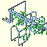
An unbalanced expansion loop. Normally a pipe loop is located midspan between anchors providing uniform displacement on each side minimizing the size of the loop. In this case an unbalanced loop is chosen to reduce the loads on the vessel nozzle by placing an axial anchor that limits axial motion next to it. The trade-off is the increase in height required for the loop. The anchor and pipe loop location is a trade-off.
An unbalanced expansion loop. Normally a pipe loop is located midspan between anchors providing uniform displacement on each side minimizing the size of the loop. In this case an unbalanced loop is chosen to reduce the loads on the vessel nozzle by placing an axial anchor that limits axial motion next to it. The trade-off is the increase in height required for the loop. The anchor and pipe loop location is a trade-off.
A tower with a guided flexible pipe connection. The guided connection allows the flexibility required in the nozzle while limiting the loads applied to the vessel nozzle. Modelling the flexibility of the nozzle and accounting for the different possible temperatures of the piping system and tower is required for successful analysis.
Pump
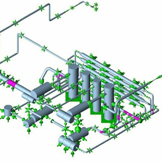
Stress analysis of a pump skid from storage towers to dual pumps. The temperature distribution of the piping varies depending on which pump or pumps are running. Here the pipes leading to the operating pump are hotter than the standby pipes. Multiple load cases are required to ensure the piping design is acceptable.
Stress analysis of a pump skid from storage towers to dual pumps. The temperature distribution of the piping varies depending on which pump or pumps are running. Here the pipes leading to the operating pump are hotter than the standby pipes. Multiple load cases are required to ensure the piping design is acceptable.
Types of Stresses in Piping Systems ⬇️
Primary, Secondary and Occasional Loads
From a piping stress analysis point of view the following are the main loads to be considered for the design:
Primary, Secondary and Occasional Loads
From a piping stress analysis point of view the following are the main loads to be considered for the design:
⬇️ Primary load occurs from Sustained loads like dead weight, live weight, internal pressure etc. and are called non-self-limiting loads. Pressure thrust from an expansion joint is used in this article.
⬇️⬇️ Secondary loads occur from thermal expansion loads like temperature change, anchors and restraints etc. and are called self-limiting loads. Thermal expansion in a horizontal pipe loop is used in this article.
⬇️⬇️⬇️ Occasional loads occur from static wind and seismic loads and are considered to act occasionally. Seismic load on a vertical pipe loop is used in this article.
⬇️⬇️ Secondary loads occur from thermal expansion loads like temperature change, anchors and restraints etc. and are called self-limiting loads. Thermal expansion in a horizontal pipe loop is used in this article.
⬇️⬇️⬇️ Occasional loads occur from static wind and seismic loads and are considered to act occasionally. Seismic load on a vertical pipe loop is used in this article.
Primary Stress ⬇️
Primary Stress is generated by internal and external force and moments. Primary stress is not self limiting – even if a part moves, the load causing it does not reduce. In this example, an expansion joint without restraining hardware creates a primary stress on a pipe.
Primary Stress is generated by internal and external force and moments. Primary stress is not self limiting – even if a part moves, the load causing it does not reduce. In this example, an expansion joint without restraining hardware creates a primary stress on a pipe.
Expansion-joint-stress
Pipe stress as reported by Caesar. The untied joint is applying a bending force, which, depending on the stress level, Caesar can report as a fail. This design does not meet the expansion joint manufacturers requirements for guiding and anchoring. The pipe with the tied joint is okay.
Pipe stress as reported by Caesar. The untied joint is applying a bending force, which, depending on the stress level, Caesar can report as a fail. This design does not meet the expansion joint manufacturers requirements for guiding and anchoring. The pipe with the tied joint is okay.