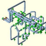
Three-dimensional beam element⬇️⬇️
The 3-D beam element behaviors are dominated by bending moments. As mentioned above, it is efficient for most analyses and sufficient for system analysis. However, there are downsides to using a 3-D beam element:
1.No localized effects will be seen on the pipe wall.
2.No second-order effects.
3.No large rotation.
4.No accounting for a large shear load.
4.1. Wall deflection occurs before bending failure.
4.2.Short, fat cantilever versus long and skinny.
5.No shell/wall effects can be seen.
The 3-D beam element behaviors are dominated by bending moments. As mentioned above, it is efficient for most analyses and sufficient for system analysis. However, there are downsides to using a 3-D beam element:
1.No localized effects will be seen on the pipe wall.
2.No second-order effects.
3.No large rotation.
4.No accounting for a large shear load.
4.1. Wall deflection occurs before bending failure.
4.2.Short, fat cantilever versus long and skinny.
5.No shell/wall effects can be seen.
The main types of piping stresses ⬇️⬇️
There are five primary piping stresses that can cause failure in a piping system: hoop stress, axial stress, bending stress, torsional stress, and fatigue stress.
Hoop stress is the result of pressure being applied to the pipe either internally or externally. Because pressure is uniformly applied to the piping system, hoop stress also is considered to be uniform over a given length of pipe. Note that hoop stress will change with diameter and wall thickness throughout the piping system. Hoop stress is most commonly represented by the following formula:
Zigma (hoop) = PD/4t
There are five primary piping stresses that can cause failure in a piping system: hoop stress, axial stress, bending stress, torsional stress, and fatigue stress.
Hoop stress is the result of pressure being applied to the pipe either internally or externally. Because pressure is uniformly applied to the piping system, hoop stress also is considered to be uniform over a given length of pipe. Note that hoop stress will change with diameter and wall thickness throughout the piping system. Hoop stress is most commonly represented by the following formula:
Zigma (hoop) = PD/4t
Axial stress⬇️⬇️
results from the restrained axial growth of the pipe. Axial growth is caused by thermal expansion, pressure expansion, and applied forces. If a pipe run can grow freely in one direction, there is no axial present—at least in theory. When comparing axial growth caused by pressure, steel-pipe growth is minimal at over 100 ft and can be ignored. Composite piping such as fiber re-enforced pipe (FRP) or plastic pipe will exhibit noticeable growth, as much as 2 to 3 in. over 100 ft under the right conditions (200 to 300 psi). The primary reason for the difference in growth rates under pressure is related to the modulus of elasticity. Steel has a modulus of elasticity of approximately 30 x 106 psi, whereas composites will be 2 to 3 orders of magnitude or less. Axial stress is represented by the axial force over the pipes cross-sectional area:
Zigma (axial) = F/A
results from the restrained axial growth of the pipe. Axial growth is caused by thermal expansion, pressure expansion, and applied forces. If a pipe run can grow freely in one direction, there is no axial present—at least in theory. When comparing axial growth caused by pressure, steel-pipe growth is minimal at over 100 ft and can be ignored. Composite piping such as fiber re-enforced pipe (FRP) or plastic pipe will exhibit noticeable growth, as much as 2 to 3 in. over 100 ft under the right conditions (200 to 300 psi). The primary reason for the difference in growth rates under pressure is related to the modulus of elasticity. Steel has a modulus of elasticity of approximately 30 x 106 psi, whereas composites will be 2 to 3 orders of magnitude or less. Axial stress is represented by the axial force over the pipes cross-sectional area:
Zigma (axial) = F/A
Bending stress⬇️⬇️
Bending stress is the stress caused by body forces being applied to the piping. Body forces are the pipe and medium weight, concentrated masses (valves, flanges), occasional forces (seismic, wind, thrust loads), and forced displacements caused by growth from adjacent piping and equipment connections. Body forces create a resultant moment about the pipe, for which the stress can be represented by the moment divided by the section modulus:
Zigma (b) = M/Z
Bending stress is the stress caused by body forces being applied to the piping. Body forces are the pipe and medium weight, concentrated masses (valves, flanges), occasional forces (seismic, wind, thrust loads), and forced displacements caused by growth from adjacent piping and equipment connections. Body forces create a resultant moment about the pipe, for which the stress can be represented by the moment divided by the section modulus:
Zigma (b) = M/Z
⬇️⬇️Torsional stress is the resultant stress caused by the rotational moment around the pipe axis and is caused by body forces. However, because a piping system most likely will fail in bending before torsion, most piping codes ignore the effects of torsion.
⬇️⬇️⬇️ Fatigue stress is created by continuous cycling of the stresses that are present in the piping. For example, turning a water faucet on and off all day will create a fatigue stress, albeit low, because of the pressure being released and then built up. In power-cycle applications, the cycling of a steam turbine from low to high pressure/temperature creates a fatigue stress. Fatigue stress results in a reduction of allowable strength in the piping system and is commonly caused by cycling of:
1. Pressure.
2. Temperature.
3. Vibration, flow induced or cause by rotating equipment.
4. Occasional loads (a gentle breeze caused the Tacoma Narrows Bridge in Washington State to collapse from fatigue).
1. Pressure.
2. Temperature.
3. Vibration, flow induced or cause by rotating equipment.
4. Occasional loads (a gentle breeze caused the Tacoma Narrows Bridge in Washington State to collapse from fatigue).
Allowable code stresses ⬇️⬇️
Piping codes, such as those published by ASME, provide an allowable code stress, which is the maximum stress a piping system can withstand before code failure. A code failure is not necessarily a piping failure. This is because of safety factors built into piping codes. ASME codes consider three distinct types of stress: sustained stress, displacement (thermal or expansion) stress, and occasional stress.
Piping codes, such as those published by ASME, provide an allowable code stress, which is the maximum stress a piping system can withstand before code failure. A code failure is not necessarily a piping failure. This is because of safety factors built into piping codes. ASME codes consider three distinct types of stress: sustained stress, displacement (thermal or expansion) stress, and occasional stress.
⬇️⬇️⬇️⬇️
Sustained or longitudinal stress is developed by imposing loads necessary to satisfy the laws of equilibrium between external and internal forces. Sustained stresses are not self-limiting. If the sustained stress exceeds the yield strength of the piping material through the entire thickness, the prevention of failure is entirely dependent on the strain-hardening properties of the material.
Sustained or longitudinal stress is developed by imposing loads necessary to satisfy the laws of equilibrium between external and internal forces. Sustained stresses are not self-limiting. If the sustained stress exceeds the yield strength of the piping material through the entire thickness, the prevention of failure is entirely dependent on the strain-hardening properties of the material.
⬇️⬇️
Displacement stress is developed by the self-constraint of the piping structure. It must satisfy an imposed strain pattern rather than being in equilibrium with an external load. Displacement stresses are most often associated with the effects of temperature; however, external displacements, such as building settlements, are considered a displacement stress.
Displacement stress is developed by the self-constraint of the piping structure. It must satisfy an imposed strain pattern rather than being in equilibrium with an external load. Displacement stresses are most often associated with the effects of temperature; however, external displacements, such as building settlements, are considered a displacement stress.
⬇️⬇️⬇️
Occasional stress is “The sum of longitudinal stresses produced by internal pressure, live and dead loads, and those produced by occasional loads,” according to ASME B31.1, paragraph 102.3.3(A). Occasional stresses can exceed the allowable code stress by a given percentage depending on frequency and duration of the load; for ASME piping codes, this is typically 15% or 20%. For example, wind loads can only exceed the allowable code stress by 15% due to their frequency, but seismic loads can exceed by 20% due to the relative infrequency of the loads.
Occasional stress is “The sum of longitudinal stresses produced by internal pressure, live and dead loads, and those produced by occasional loads,” according to ASME B31.1, paragraph 102.3.3(A). Occasional stresses can exceed the allowable code stress by a given percentage depending on frequency and duration of the load; for ASME piping codes, this is typically 15% or 20%. For example, wind loads can only exceed the allowable code stress by 15% due to their frequency, but seismic loads can exceed by 20% due to the relative infrequency of the loads.
⬇️⬇️⬇️
Pressure design basics
As a pipe stress analyst, it is critical to understand how wall thickness is determined. If the pipe wall is too thin, it will not matter how the pipe is supported; it will fail. Typically, the engineer designing the system also will determine the wall thickness; however, the wall thickness is also verified during the pipe stress analysis. Most engineers are more concerned with mass flow and pressure drop, therefore the effects of pipe size and wall thickness may be lost on them. Going to a thicker pipe wall or a larger pipe size may be worth the material costs, versus facing design issues and added pipe-support costs in labor and materials.
Pressure design basics
As a pipe stress analyst, it is critical to understand how wall thickness is determined. If the pipe wall is too thin, it will not matter how the pipe is supported; it will fail. Typically, the engineer designing the system also will determine the wall thickness; however, the wall thickness is also verified during the pipe stress analysis. Most engineers are more concerned with mass flow and pressure drop, therefore the effects of pipe size and wall thickness may be lost on them. Going to a thicker pipe wall or a larger pipe size may be worth the material costs, versus facing design issues and added pipe-support costs in labor and materials.
Basic of Caesar 2 API610 analysis ⬇️
Module 2, Pulsations and Other Forces in a Reciprocating Compressor ⬇️⬇️
This media is not supported in your browser
VIEW IN TELEGRAM
Caesar II: input basics 1
This media is not supported in your browser
VIEW IN TELEGRAM
Caesar II:input basics 2
This media is not supported in your browser
VIEW IN TELEGRAM
Caesar II:input basics 3
This media is not supported in your browser
VIEW IN TELEGRAM
Caesar II:input basics 4