A common mistake is to extend the 10-in process line over the rack bent and cap it, when the line should have been run as if a support problem did not exist.
A smaller piece of pipe or dummy leg could then be welded to the elbow for support (a hole should not be cut in the process line).
A smaller piece of pipe or dummy leg could then be welded to the elbow for support (a hole should not be cut in the process line).
Supporting of Pipes of a Distillation Tower ⬇️⬇️⬇️
Supporting of pipes on a distillation tower is a critical activity involving stress analysis of almost all lines. Following points must be taken care of while supporting pipes of a distillation tower.
Piping shall be grouped as far as possible for the ease of supports. Piping shall be supported from cleats welded on the vessel as far as possible. Proper guides at recommended intervals shall be provided for long vertical lines.
Piping support cleats for safety valves shall be independent meant for safety valves only & shall be designed considering impact loading during popping off. Utility Connection nozzles shall be from side/top.
Piping support cleats for safety valves shall be independent meant for safety valves only & shall be designed considering impact loading during popping off. Utility Connection nozzles shall be from side/top.
The stress analysis requirements for supports and guides in piping connected to distillation towers and vertical vessels are as follows : ⬇️
1. The rest support must be as close as possible to nozzle. If there is a horizontal spool immediately adjacent to the nozzle, the rest support will be done shown in the sketch below.
2. The guides along the vertical run will be spaced as shown in the sketch below.
3. Ease of erection is also to be considered when positioning and spacing the guides, therefore it will be useful grouping the guides for a number of pipes at a common elevation. This criteria is valid also for columns with reinforcing rings, whereby positioning the guides on the rings, it is not necessary the welding on the shell.
4. For larger diameter piping (NPS >= 16″) standard distances between the guides are not established since support system is generally based on the stress analysis requirements.
1. The rest support must be as close as possible to nozzle. If there is a horizontal spool immediately adjacent to the nozzle, the rest support will be done shown in the sketch below.
2. The guides along the vertical run will be spaced as shown in the sketch below.
3. Ease of erection is also to be considered when positioning and spacing the guides, therefore it will be useful grouping the guides for a number of pipes at a common elevation. This criteria is valid also for columns with reinforcing rings, whereby positioning the guides on the rings, it is not necessary the welding on the shell.
4. For larger diameter piping (NPS >= 16″) standard distances between the guides are not established since support system is generally based on the stress analysis requirements.
caesar-tutorial-1.pdf
4.2 MB
caesar-tutorial-1.pdf
Design_and_Analysis_of_Piping_System.pdf
295.8 KB
Design-and-Analysis-of-Piping-System-with-Supports-Using-CAESAR-II.pdf
How to perform a pipe stress analysis ⬇️⬇️
Understanding the various types of pipe stresses, the process, and best practices are necessary to perform effective pipe stress analyses.
Understanding the various types of pipe stresses, the process, and best practices are necessary to perform effective pipe stress analyses.
Pipe stress analysis is an analytical method to determine how a piping system behaves based on its material, pressure, temperature, fluid, and support. Pipe stress analysis is not an accurate depiction of the piping behavior, but it is a good approximation.
The analytical method can be by inspection, simple to complex hand calculations, or a computer model. The computer models can vary from 1-D beam elements to complex, finite element models. For instance, if it is a water system with no outside forces applied to the piping system, inspection or hand calculations are usually sufficient. If it is a high-pressure, high-temperature, hazardous-fluids system, and/or large outside forces are applied to the piping system, a computer-aided model may be required.
Understanding pipe stress analysis software does not make for a solid foundation of pipe stress analysis. It’s important to understand the various types of pipe stresses, the process, and other items related to pipe stress analysis for best practices in performing a pipe stress analysis.
There are many piping codes and standards that could be used during a pipe stress analysis depending on the application (power, process chemical, gas distribution) and location (country or local jurisdiction). However, to keep things simple, this discussion is based on American Society of Mechanical Engineers (ASME) B31.1 Power Piping. The physics of pipe stress analysis does not change with piping code.
Pipe stress analysis should be done primarily to provide safety to the public, whether you are designing a building heating system or a high-pressure gas line in a refinery. Public safety is paramount. The National Society of Professional Engineers (NSPE) Code of Ethics’ first cannon is: “Hold paramount the safety, health, and welfare of the public.”
On a good day😂😂, a pipe failure is only a broken support that the owner does not call the designer/engineer about.
On a bad day😢😢, the owner requires the designer/engineer to pay for the damage and the engineer to provide a solution for free.
On a horrible day😱😱, someone is killed.
On a bad day😢😢, the owner requires the designer/engineer to pay for the damage and the engineer to provide a solution for free.
On a horrible day😱😱, someone is killed.
Another reason a pipe stress analysis is performed is to increase the life of piping. Most engineers won’t consider a piece of pipe to be equipment, but it is no different than a pump. Both have moving parts and must be designed and maintained properly to ensure a proper life. Pipe stress analysis also is used to protect equipment, because a pipe is nothing more than a big lever arm connected to a delicate piece of equipment. If not properly supported and designed, it can have devastating effects on that equipment.
There are several common reasons that could warrant a pipe stress analysis, in addition to those above.
They include:
1.Elevated temperatures (>250°F).
2.Pressure mandated (300 psig).
3.Sensitive equipment connections.
4.Large D/t ratio (>50).
5.Piping subject to external pressures.
6.Critical services.
The key when performing a pipe stress analysis is determining the required level of detail.
They include:
1.Elevated temperatures (>250°F).
2.Pressure mandated (300 psig).
3.Sensitive equipment connections.
4.Large D/t ratio (>50).
5.Piping subject to external pressures.
6.Critical services.
The key when performing a pipe stress analysis is determining the required level of detail.
How to model the piping system⬇️⬇️⬇️
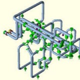
Pipe stress analysis computer models are a series of 3-D beam elements that create a depiction of the piping geometry. Three-dimensional beam elements are the most efficient way to model the piping system, but not necessarily the most accurate; and without complex finite element models, it is nearly impossible to account for everything. However, it is known from historical empirical testing that these methods and 3-D beam computer models demonstrate enough behavior that they are a good approximation. In addition, piping codes, such as ASME B31, have safety margins that allow for approximation. That being said, there are some pitfalls with modeling piping systems that one should avoid:
The computer models are only as good as the information entered into them. It is important when developing a pipe stress analysis, as with any finite element analysis (FEA) model, to also understand the physics and boundary conditions of the model.
Elements used to model the piping system have their limitations. One-dimensional beam elements are great for straight pieces of piping, but not so good with pipe fittings (elbows, tees, reducers, etc.). Therefore, ASME has developed stress-intensification factors (SIFs) for piping fittings through empirical testing. They allow for greater approximation without using complex FEA models with shells, plates, and brick elements.
It is important to make sure these limitations are considered when developing a pipe stress analysis. Most pipe stress analyses do not perform like a high-powered FEA software package.
Pipe stress analysis computer models are a series of 3-D beam elements that create a depiction of the piping geometry. Three-dimensional beam elements are the most efficient way to model the piping system, but not necessarily the most accurate; and without complex finite element models, it is nearly impossible to account for everything. However, it is known from historical empirical testing that these methods and 3-D beam computer models demonstrate enough behavior that they are a good approximation. In addition, piping codes, such as ASME B31, have safety margins that allow for approximation. That being said, there are some pitfalls with modeling piping systems that one should avoid:
The computer models are only as good as the information entered into them. It is important when developing a pipe stress analysis, as with any finite element analysis (FEA) model, to also understand the physics and boundary conditions of the model.
Elements used to model the piping system have their limitations. One-dimensional beam elements are great for straight pieces of piping, but not so good with pipe fittings (elbows, tees, reducers, etc.). Therefore, ASME has developed stress-intensification factors (SIFs) for piping fittings through empirical testing. They allow for greater approximation without using complex FEA models with shells, plates, and brick elements.
It is important to make sure these limitations are considered when developing a pipe stress analysis. Most pipe stress analyses do not perform like a high-powered FEA software package.