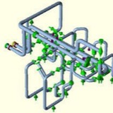
The flexibility model does not need to be a model of the complete piping system. The compressor
packager’s stress analyst shall generate a detailed model of their piping and a simplified model of a
portion of the EC’s piping to evaluate the interaction between the piping system. The packager’s stress
analyst does not need to model the complete pipe system designed by the EC. Knowing how to
simplify the model of the EC piping takes the understanding of an experienced pipe stress analyst.
packager’s stress analyst shall generate a detailed model of their piping and a simplified model of a
portion of the EC’s piping to evaluate the interaction between the piping system. The packager’s stress
analyst does not need to model the complete pipe system designed by the EC. Knowing how to
simplify the model of the EC piping takes the understanding of an experienced pipe stress analyst.
Similarly, the EC’s stress analyst shall generate a detailed model of their piping and a simplified
model of the compressor packager’s piping to evaluate the interaction of the overall piping system.
model of the compressor packager’s piping to evaluate the interaction of the overall piping system.
The owner may wish to specify that a single party conduct the flexibility analysis of the complete
system rather than separate parties duplicating their efforts. The approach of a single party doing the
flexibility analysis parallels the API 618, 5th Edition recommendation that a single party conduct the
flexibility analysis and the vibration analysis. The effort to model the piping is minimized when these
studies are done by the same party. Also, the competing interests of the flexibility and vibration
analysis can be best resolved when these studies are done by one party.
system rather than separate parties duplicating their efforts. The approach of a single party doing the
flexibility analysis parallels the API 618, 5th Edition recommendation that a single party conduct the
flexibility analysis and the vibration analysis. The effort to model the piping is minimized when these
studies are done by the same party. Also, the competing interests of the flexibility and vibration
analysis can be best resolved when these studies are done by one party.
Spring hanger selection and design guidelines for a Piping engineer using Caesar II
Spring hangers are an integrated part of Piping Industry. The use of spring hangers for supporting pipe weights is well-known to every piping engineer. Whenever some rigid supports are not taking load due to its thermal movement or rigid supports are creating bad effect to equipment connection Piping engineers suggest the use of a spring hanger to share some of the loads and to keep the piping system safe.
Selection of the appropriate type of hanger support for any given application is governed by the individual piping configuration and job requirements.
Selection of the appropriate type of hanger support for any given application is governed by the individual piping configuration and job requirements.
a) Variable Spring Hanger: Loads vary throughout its operating range
b) Constant Spring hanger: Load remains constant throughout its operating range.
The following write up will provide a simple guideline for selection of both Variable and constant spring hanger while analyzing a piping system using Caesar II:
Selection Procedure of Variable Effort Springs:
1. Determine the hot load required and the pipe movement (up or down).
2. Estimate the travel range from the catalogue.
3. Select the smallest spring size which has the hot load within the working travel (mid range).
4. Ensure that the cold load lies within the working range of the spring i.e. between the two dark black lines shown in the selection chart.
Calculate the cold load as follows:
Cold Load = Operating Load + Movement x Spring Rate (For pipe movement up)
Cold Load = Operating Load – Movement x Spring Rate (For pipe movement down)
5. If the Cold load lies beyond the working range in the selection chart, then select higher spring size or the next travel range.
6. Check the variability in selected spring
1. Determine the hot load required and the pipe movement (up or down).
2. Estimate the travel range from the catalogue.
3. Select the smallest spring size which has the hot load within the working travel (mid range).
4. Ensure that the cold load lies within the working range of the spring i.e. between the two dark black lines shown in the selection chart.
Calculate the cold load as follows:
Cold Load = Operating Load + Movement x Spring Rate (For pipe movement up)
Cold Load = Operating Load – Movement x Spring Rate (For pipe movement down)
5. If the Cold load lies beyond the working range in the selection chart, then select higher spring size or the next travel range.
6. Check the variability in selected spring
Generally for non critical systems, the variability is limited to 25% throughout the total travel. For critical systems such as steam connections terminating at turbines and pipes connected to rotating equipment:
Like compressor etc. variability is limited to 10%. If the variation exceeds the allowed value, choose higher size spring or smaller spring rate at same load range.
7. Select the type and check the feasibility of the spring depending on space available and type of structure available.
Like compressor etc. variability is limited to 10%. If the variation exceeds the allowed value, choose higher size spring or smaller spring rate at same load range.
7. Select the type and check the feasibility of the spring depending on space available and type of structure available.
Selection procedure of Constant effort springs:
Constant Effort spring shall be selected where the vertical movement exceeds 50 mm, or where it is necessary to restrict transfer of load to adjacent terminal of equipment or where the spring variability exceeds 25%.
Constant Effort spring shall be selected where the vertical movement exceeds 50 mm, or where it is necessary to restrict transfer of load to adjacent terminal of equipment or where the spring variability exceeds 25%.
1. Determine the load and the total movement.
Total movement = design movement + over travel
Over travel = 20% of the design movement or 25mm whichever is higher.
2. Select the spring from the load chart keeping in mind that the spring selected must lie within the working range
3. Select the type and check the feasibility of the spring depending on space available and type of structure available.
4. The Spring box must be able to move freely without any restriction.
5. Stress Engineer must check the eccentricity (See Fig 1 below) of the spring load flange and the spring base plate while providing foundation information to civil.
Total movement = design movement + over travel
Over travel = 20% of the design movement or 25mm whichever is higher.
2. Select the spring from the load chart keeping in mind that the spring selected must lie within the working range
3. Select the type and check the feasibility of the spring depending on space available and type of structure available.
4. The Spring box must be able to move freely without any restriction.
5. Stress Engineer must check the eccentricity (See Fig 1 below) of the spring load flange and the spring base plate while providing foundation information to civil.
Spring Selection procedure in Caesar II:
1. CAESAR-II Default Setting for Hanger Selection:
Before making input for spring selection it is always better to make a default Caesar setting for hanger design.
1. CAESAR-II Default Setting for Hanger Selection:
Before making input for spring selection it is always better to make a default Caesar setting for hanger design.
2. CAESAR-II Auxiliary Spreadsheet setting for Hanger Selection
During spring selection at a particular node the following auxiliary spreadsheet appears. The setting of this spreadsheet is to be done as illustrated in below diagram.
During spring selection at a particular node the following auxiliary spreadsheet appears. The setting of this spreadsheet is to be done as illustrated in below diagram.