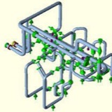
Rubber expansion joints have been specified and successfully used for many years to accommodate pressure loads, relieve movement stresses, reduce noise, isolate vibration, compensate for misalignment after plants go on stream and prolong the life of pumps and other motive equipment. Once in service, the flexible rubber expansion joint should be protected from any ozone generating processes such as nearby welding. Proper storage in a cool dry location prior to installation will help lengthen service life.
Note:
In a properly designed pipeline, only one axial expansion joint between 2 fixed points must be provided. The spring rate of the metal bellows cannot withstand the pressure reaction force, caused by the internal pressure. If the fixed point is not dimensioned correctly, then the piping system is pushed apart.
In a properly designed pipeline, only one axial expansion joint between 2 fixed points must be provided. The spring rate of the metal bellows cannot withstand the pressure reaction force, caused by the internal pressure. If the fixed point is not dimensioned correctly, then the piping system is pushed apart.
Expansion joint presetting ⏬
In order to increase axial movement, the expansion joint can be presetted to its maximum extension during installation. For expansion joints with swivel flange there is a risk during the extension that the sealing bulge will spring from the groove of the backing flange. If presettings of more than 10 mm are needed, a flange connection will need to be disconnected at another location. Now the expansion joint can be installed relaxed and the flange disconnection sites that were opened before can be closed again.
In order to increase axial movement, the expansion joint can be presetted to its maximum extension during installation. For expansion joints with swivel flange there is a risk during the extension that the sealing bulge will spring from the groove of the backing flange. If presettings of more than 10 mm are needed, a flange connection will need to be disconnected at another location. Now the expansion joint can be installed relaxed and the flange disconnection sites that were opened before can be closed again.
n order to increase lateral movement, the expansion joint can be presetted to its maximum lateral displace- ment against the direction of movement during installation. During operation, it will move back to the opposite side through the zero point. In this way, the lateral movement can be increased by up to 100%. For expansion joints with swivel flange there is a risk during displacement that the sealing bulge will spring from the groove of the backing flange. If presettings of more than 5 mm are needed, a flange connection will need to be disconnected at another location. Now the expansion joint can be installed relaxed and the flange disconnection sites that were opened before can be closed again.