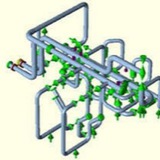
Surge Analysis ⏬
When your process or production system is at continuous operation, the pressures and flow rates are constant. For normal operating conditions, the piping system is able to withstand the resulting stresses.
However, when a sudden event occurs, like valve operations, a tripping pump or failure of equipment, the steady-state fluid flow is disturbed. One consequence may be excessive surge pressures and consequently an increase in pipe stress and loads.
When your process or production system is at continuous operation, the pressures and flow rates are constant. For normal operating conditions, the piping system is able to withstand the resulting stresses.
However, when a sudden event occurs, like valve operations, a tripping pump or failure of equipment, the steady-state fluid flow is disturbed. One consequence may be excessive surge pressures and consequently an increase in pipe stress and loads.
Without careful timing of valves, the occurring surge pressures can easily reach tens of bars. For fiberglass systems such overpressure may cause the pipe to fail, especially joints and flanges are sensitive for overpressure. During a transient event low (negative) pressures may also occur. Large diameter fiberglass systems are especially sensitive to low or sub-atmospheric pressures as they are prone to buckling.
Possible mitigation measures for non-vacuum resistant piping are changes to how the system is operated or the introduction of adequately sized buckling rings.
We can act as a very capable partner to analyze your system from a dynamical perspective considering water hammer and pressure surges. When problems are found we closely discuss how to resolve the issues by carefully selecting any counter measures like the incorporation of surge vessels, vacuum breakers, air valve or a rerouting of a part of the piping system.
The successful installation of expansion joints in a pipe system requires the careful consideration of many variables.
The most important issue is to establish the direction in which the movements are acting and in which way the movements should be absorbed. Once this information is known, the solution incorporating the most suitable expansion joint type(s) can be determined.
The most important issue is to establish the direction in which the movements are acting and in which way the movements should be absorbed. Once this information is known, the solution incorporating the most suitable expansion joint type(s) can be determined.
Fix points and guides for axial expansion joints⬇️
It is important that the fix point is placed as close to the axial expansion joint as possible. It is important to note that only one axial expansion joint can be installed between two fix points. The distance between the expansion joint and the first guide should be a maximum of 4 x diameter. The distance between the following guides should be 14-20 x diameter.
This is illustrated in the drawings below.
It is important that the fix point is placed as close to the axial expansion joint as possible. It is important to note that only one axial expansion joint can be installed between two fix points. The distance between the expansion joint and the first guide should be a maximum of 4 x diameter. The distance between the following guides should be 14-20 x diameter.
This is illustrated in the drawings below.
For other expansion joint types, the position of fix points and guides are dependent on the pipe system and the position of the expansion joint in the pipe system.
AXIAL Expansion joint selection⬇️
This illustrates the importance in the use of the three fix points, as the use of two or more axial expansion joints in a piping section will create an undetermined arrangement.
The amount of movements imposed on each expansion joint is not controlled, as the pipe between the two bellows can move sideward freely in both directions depending on the friction of the pipe supports and the di Rerences in stiRness between the bellows. It is always important to have one axial expansion joint between two fix points.
This illustrates the importance in the use of the three fix points, as the use of two or more axial expansion joints in a piping section will create an undetermined arrangement.
The amount of movements imposed on each expansion joint is not controlled, as the pipe between the two bellows can move sideward freely in both directions depending on the friction of the pipe supports and the di Rerences in stiRness between the bellows. It is always important to have one axial expansion joint between two fix points.
⬆️⬆️⬆️⬆️The piping system should be divided into sections by means of fix points, guides or restraining tie rods in order to have only one expansion joint per section of straight pipe system. The fix points and other restraining devices should be designed for the full pressure thrust from the bellows eRective area plus the bellows displacement force. Additionally, the forces generated by the friction within the guides should also be considered.