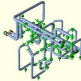
Local Stresses and Code Requirements ⬇️
The local stresses SL, SL1, SL2, SL3 can be expressed as follows:
SL = local stress due to deadweight, psi
SL1 = local stress due to deadweight, seismic inertia, and other dynamic loads, psi
SL2 = local stress due to thermal expansion and seismic anchor movement, psi
SL3 = local stress due to concurrently acting loads, psi
The local stresses SL, SL1, SL2, SL3 can be expressed as follows:
SL = local stress due to deadweight, psi
SL1 = local stress due to deadweight, seismic inertia, and other dynamic loads, psi
SL2 = local stress due to thermal expansion and seismic anchor movement, psi
SL3 = local stress due to concurrently acting loads, psi
Strictly speaking, the present piping codes give no specific limits for local stresses. As an industry practice, the calculated local stress is added to the general pipe stress and then compared with the pipe stress allowables specified by the applicable code. As an example, the total (general plus local) pipe stresses for ASME Class 2 and 3 piping shall satisfy the following equations ⬇️
Local Stresses⏬
1. Design loading
2. Service loadings
3. Sustained and thermal expansion loading
4. Local stress limit loading
1. Design loading
2. Service loadings
3. Sustained and thermal expansion loading
4. Local stress limit loading
Local Stress Due to Restraint of Pipe Radial Expansion⬇️
The membrane and flexural stresses can be calculated as follows⏬
In the case of the local stress produced by restraint to the pipe radial expansion SL = SL1 = 0, For fillet weld, i = 2.1 should be used. In addition, the stress check on limit loading is required. Here, SL3 = SL2.
Local Stress Due to Contact⬇️
The membrane and flexural stresses can be calculated as follows:
The membrane and flexural stresses can be calculated as follows:
Other Types of Local Stresses ⏬
The two types of local stresses previously described are commonly encountered by stress analysts. Detailed descriptions and analysis methods for other types of local stresses such as the local stresses at integral welded attachments to pipe (e.g., lugs and trunnions) can be found in technical publications, Welding Research Council Bulletins 107 and 198, and ASME Code Cases.
The two types of local stresses previously described are commonly encountered by stress analysts. Detailed descriptions and analysis methods for other types of local stresses such as the local stresses at integral welded attachments to pipe (e.g., lugs and trunnions) can be found in technical publications, Welding Research Council Bulletins 107 and 198, and ASME Code Cases.
ANALYSIS OF INTEGRAL WELDED ATTACHMENTS (IWA)⬇️
Integral Welded Attachments are often used to support piping systems. The local stresses in the piping at IWA locations are commonly evaluated using the Welding Research Council (WRC) Bulletin #107 approach,21 which is based on Bijlaard’s work. Generally.
Integral Welded Attachments are often used to support piping systems. The local stresses in the piping at IWA locations are commonly evaluated using the Welding Research Council (WRC) Bulletin #107 approach,21 which is based on Bijlaard’s work. Generally.
The various methods for local stress evaluations can be categorized in accordance with the following list. (Friction-induced loads due to weight and thermal expansion, if applicable, should be included.)
1. Stress intensification factor (SIF) approach for certain configurations
2. WRC Bulletin #107 approach with limitation on ß (attachment parameter) and γ (shell parameter) parameters
3. ASME Code cases approach
4. Approach based on utilization of any available finite element analysis (FEA) results or published data
5. Rigorous FEA approach
1. Stress intensification factor (SIF) approach for certain configurations
2. WRC Bulletin #107 approach with limitation on ß (attachment parameter) and γ (shell parameter) parameters
3. ASME Code cases approach
4. Approach based on utilization of any available finite element analysis (FEA) results or published data
5. Rigorous FEA approach