Vibration of piping systems may be induced by internal pipe flow behavior such as pulsation, two phase and turbulence or external pipe flow such as wind. Such piping vibration is generally termed “Flow Induced Vibration (FIV)” and has a potential to cause damage of the piping systems. It is therefore important to reflect the expected FIV characteristics into design of the piping system including pipe supports. For this purpose, piping vibration analysis is indispensable technology to ensure design soundness or to investigate counter-measures against FIV.
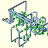
Severe resonant vibration was expected by pulsation analysis at piping system connecting to reciprocating compressors (Fig.1). The dominant excitation frequencies due to pulsation were expected to be less than 22Hz. However, the lowest piping mechanical natural frequency in original support design was 8Hz although this frequency should be fully higher than the excitation frequency threshold of 22Hz. It was judged necessary to provide additional pipe supports and to make some support type change in order to prevent resonance between piping mechanical natural frequencies and dominant pulsation frequencies. In the piping system reflecting such design improvement (Fig.2), no severe vibration was observed during plant’s commercial operation.
CAESAR II 2018 (Version 10.00)⬇️
New and extended capabilities have been added to the latest version of CAESAR II, version 10.00 – 2018.
The software has been updated to B31.3-2016, EN-13480 (2016), B31.8-2016, B31.8 Ch VIII 2016.
Other piping and equipment codes support have been updated, like B31.3 Chapter IX (high pressure piping) and Kouatsu-Gas Hoan Kyoukai KHK level II seismic analysis.
Is now possible to identify supports, by using the new support tag field in the extended Restraint auxiliary panel, where two additional restraint definitions have been added. In this way all the six degrees of freedom of a support can be described in one single panel.
A tag hanger field has been added to the Hanger input list as well.
Very interesting is the Element name or in the Piping Input Window or in the Elements list input.
You can choose to show supports and hanger tags and element name in the graphic view.
Other two fields have been added to hangers and support lists, in order to read and import data from PCF files and to export through output reports and MDB output tables.
This topic will be discussed in the second part of this article.
A number of important enanchements in Piping Input:
- new find and replace function (in the right-click menu) added in the List dialog.
- when a pipe element in deleted is no more necessary to reset the coordinates
- is now possible to display the North arrow in both Classic Piping Input and Static Output Processor
- Previous and Invert options
- Added Mill Tolerance icon and new Mill Tolerance options
- When load cases are deleted in the Load case editor, the remaining load cases are renumbered after a windows shows the load cases and their dependents that will be deleted or revised.
New and extended capabilities have been added to the latest version of CAESAR II, version 10.00 – 2018.
The software has been updated to B31.3-2016, EN-13480 (2016), B31.8-2016, B31.8 Ch VIII 2016.
Other piping and equipment codes support have been updated, like B31.3 Chapter IX (high pressure piping) and Kouatsu-Gas Hoan Kyoukai KHK level II seismic analysis.
Is now possible to identify supports, by using the new support tag field in the extended Restraint auxiliary panel, where two additional restraint definitions have been added. In this way all the six degrees of freedom of a support can be described in one single panel.
A tag hanger field has been added to the Hanger input list as well.
Very interesting is the Element name or in the Piping Input Window or in the Elements list input.
You can choose to show supports and hanger tags and element name in the graphic view.
Other two fields have been added to hangers and support lists, in order to read and import data from PCF files and to export through output reports and MDB output tables.
This topic will be discussed in the second part of this article.
A number of important enanchements in Piping Input:
- new find and replace function (in the right-click menu) added in the List dialog.
- when a pipe element in deleted is no more necessary to reset the coordinates
- is now possible to display the North arrow in both Classic Piping Input and Static Output Processor
- Previous and Invert options
- Added Mill Tolerance icon and new Mill Tolerance options
- When load cases are deleted in the Load case editor, the remaining load cases are renumbered after a windows shows the load cases and their dependents that will be deleted or revised.
In addition to the general pipe stresses (the pressure stress and the moment stress) as described in the previous sections, there are certain local pipe wall stresses produced by:
(1) restraint of the pipe radial thermal and internal pressure expansion of pipethrough- structural-steel type of anchors.
(2) the transfer of load from the supporting surface to the pipe surface over a contact length along the axis of the pipe.
(3) attachments welded to pipe (e.g., lugs and trunnions).
(1) restraint of the pipe radial thermal and internal pressure expansion of pipethrough- structural-steel type of anchors.
(2) the transfer of load from the supporting surface to the pipe surface over a contact length along the axis of the pipe.
(3) attachments welded to pipe (e.g., lugs and trunnions).
Local Stresses and Code Requirements ⬇️
The local stresses SL, SL1, SL2, SL3 can be expressed as follows:
SL = local stress due to deadweight, psi
SL1 = local stress due to deadweight, seismic inertia, and other dynamic loads, psi
SL2 = local stress due to thermal expansion and seismic anchor movement, psi
SL3 = local stress due to concurrently acting loads, psi
The local stresses SL, SL1, SL2, SL3 can be expressed as follows:
SL = local stress due to deadweight, psi
SL1 = local stress due to deadweight, seismic inertia, and other dynamic loads, psi
SL2 = local stress due to thermal expansion and seismic anchor movement, psi
SL3 = local stress due to concurrently acting loads, psi
Strictly speaking, the present piping codes give no specific limits for local stresses. As an industry practice, the calculated local stress is added to the general pipe stress and then compared with the pipe stress allowables specified by the applicable code. As an example, the total (general plus local) pipe stresses for ASME Class 2 and 3 piping shall satisfy the following equations ⬇️