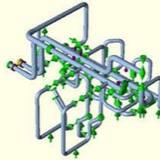
3) In a pressurized buried pipeline such as a water main or sewage force main, thrust forces act on the pipe where changes in fluid velocity, changes in pipe size or changes in pipeline direction occur. This is generally at fittings such as plugs, caps, valves, tees, bends or reducers.
4) Thrust forces may also occur at the locations where new pipe is connected in-line to a different type of existing pipe with different sealing diameters. A significant example of this is the connection of large diameter Prestressed Concrete Cylinder Pipe (PCCP) and Ductile Iron Pipe (DIP). A thrust force is created at this type of connection in the same manner as a reducer, see Unbalanced Thrust at Connections to Existing Water Pipelines, in this section.
General Requirements for Concrete Thrust Blocks ⬇️
1) Always consider the thrust forces in the design of buried pressurized pipelines, since it may cause separation of the joints and leakage of the pipeline. The most fundamental approach to resist a thrust force is to install a non-reinforced poured-in-place concrete block at the fitting.
2) The basic type of non-reinforced concrete block used for bends, tees, plugs and caps is referred to here as a concrete thrust block, but may also be referred to as an anchorage or buttress.
3) When concrete thrust blocks are used for fittings in close proximity to each other, ensure that no part of the blocks overlap and that the passive pressure soil zones do not overlap which could cause construction problems or block failure. See Passive Soil Pressure for Concrete Thrust Blocks, in this section.
4) Locate the thrust block such that its passive pressure zone of influence does not affect other
utilities or structures.
5) Provide a minimum soil cover of one (1) foot over all thrust blocks. For thrust blocks in existing or proposed roads or road rights of way, provide a minimum one and one half (1-1/2) feet of soil cover, unless otherwise directed or approved.
1) Always consider the thrust forces in the design of buried pressurized pipelines, since it may cause separation of the joints and leakage of the pipeline. The most fundamental approach to resist a thrust force is to install a non-reinforced poured-in-place concrete block at the fitting.
2) The basic type of non-reinforced concrete block used for bends, tees, plugs and caps is referred to here as a concrete thrust block, but may also be referred to as an anchorage or buttress.
3) When concrete thrust blocks are used for fittings in close proximity to each other, ensure that no part of the blocks overlap and that the passive pressure soil zones do not overlap which could cause construction problems or block failure. See Passive Soil Pressure for Concrete Thrust Blocks, in this section.
4) Locate the thrust block such that its passive pressure zone of influence does not affect other
utilities or structures.
5) Provide a minimum soil cover of one (1) foot over all thrust blocks. For thrust blocks in existing or proposed roads or road rights of way, provide a minimum one and one half (1-1/2) feet of soil cover, unless otherwise directed or approved.
numerical simulation of strength failure of buried polyethylene pipe under foundation settlement ⬇️
The failure mode for polyethylene pipes could be different, ranging from ductile failure to brittle failure. More precisely, as shown in Fig. 1, in addition to yielding, rupturing, impact and stress cracking are also among the most common causes of failure in polyethylene pipes and do not necessarily happen after the yielding.
There are two principle methods to analyze buried structures under the ground displacement. In the first method, which is the direct method, the load (i.e. external load and settlement) is applied on the soil environment, the whole model is analyzed in each step, and the response of the model is calculated (Fig. 2a).