Matching Valve Dynamics to Application
Requirements
Selecting the optimal valve type is crucial for system integrity, flow control precision, and long-term operational performance. Here is a breakdown of 8 primary valve configurations and their primary industrial applications:
1 Ball Valve: Low operating torque and tight seal; optimal for rapid quarter-turn isolation.
2 Butterfly Valve: Space-saving design with lower face-to-face dimensions, ideal for high-flow, large-diameter piping.
3 Gate Valve: Full-bore design delivering minimum fluid friction and negligible pressure drop in full-open conditions.
4 Globe Valve: Linear motion design offering accurate throttling and stable flow regulation.
5 Check Valve: Self-actuating uni-directional valve to prevent dynamic backflow and hydraulic shock.
6 Solenoid Valve: Electromechanical control for high-speed automated process switching and pilot actuation.
7 Diaphragm Valve: Isolated media pathway designed for cleanroom operations or highly aggressive
❤4
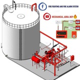
Fire-fighting and Fire Alarm system 👷🏻🧰
Photo
#ChilledWater100
Day 71: Pressure Loss in Pipe Runs ❗
Where there is energy, there is inefficiency; that's a law of life. And life wouldn't possibly exclude chilled water piping networks, and piping in general, from this law.
As fluid flows inside a pipe, it rubs against the surface of the pipe, and among itself. This friction causes a dissipation of flow energy into thermal energy.
Loss of flow energy means loss of pressure. The more fluid flows inside a pipe, the more pressure it loses.
To calculate pressure loss, multiple formulas have been presented. The three most commonly used (being the most accurate) formulas are:
1. Darcy Weisbach
2. Hazen Williams
3. Manning
The three equations share one thing in common:
Pressure loss = Function of (Pipe diameter, Length and Flow Rate)
Hazen Williams and Manning equations were developed empirically, meaning from experimentation, rather than from direct theory. They're used in situations where the diameter of a pipe is to be calculated from a fixed pressure loss value.
However, this doesn't have to be the case in chilled water systems. Most of the time, you'll be calculating pressure loss in a pipe of known diameter, length and flow.
Darcy Weisbach is the most accurate formulation, but it requires the use of a diagram called Moody's diagram.
In the Darcy Weisbach's formula, there's a factor called "friction factor", or f. f is a function of pipe material, diameter, fluid properties and flow velocity.
f is obtained from Moody's diagram based on a fixed Reynold's number and relative roughness.
Re = density * velocity * diameter / dynamic viscosity
ε/D = pipe roughness / diameter
f = function of (Re, ε/D)
Hf = Head loss due to friction
= function of (D, L, V, f)
D: Pipe's internal diameter
L: Length
V: Flow Velocity
f: Friction factor, obtainable from Moody's diagram
If you like learning about chilled water systems, follow me and stay tuned for my daily post.
#hvac #ChilledWater #datacenter #engineering #HVACDesign
❤3
This media is not supported in the widget
VIEW IN TELEGRAM
Fire-fighting and Fire Alarm system 👷🏻🧰
1790346606329.pdf
Piping Inspections 👆
This media is not supported in the widget
VIEW IN TELEGRAM
❤1
Fire-fighting and Fire Alarm system 👷🏻🧰
Photo
Detailed HVAC Chiller System – Chilled Water & Condenser Water Circulation
A complete HVAC chiller system showing the chilled-water loop, condenser-water loop, cooling tower, AHU, FCUs, pumps, evaporator, condenser, and screw compressors. 🌬️❄️🔥
#HVAC #ChillerSystem #HVACTechnician #ChilledWater #CoolingTower #AHU #FCU #Refrigeration #HVACEngineering #TechnicalDiagram
A complete HVAC chiller system showing the chilled-water loop, condenser-water loop, cooling tower, AHU, FCUs, pumps, evaporator, condenser, and screw compressors. 🌬️❄️🔥
#HVAC #ChillerSystem #HVACTechnician #ChilledWater #CoolingTower #AHU #FCU #Refrigeration #HVACEngineering #TechnicalDiagram
❤1
Welding Positions - 1F to 6F & 1G to 6G | Technical
Overview
Understanding welding positions is essential for achieving proper weld quality, penetration, fusion and overall joint integrity in fabrication and piping works
FILLET WELDING POSITION
1F Flat Position
The weld is deposited from the upper side of the joint.
The welding surface is generally horizontal, making it one of the easiest positions for achieving good weld control.
❤3